Navigation : EXPO21XX > SENSORS & CONTROLS 21XX >
H38: Electricity Sensors
> e+a Elektromaschinen und Antriebe
e+a Elektromaschinen und Antriebe


- Offer Profile
- e+a Elektromaschinen und Antriebe was founded in 1981 and
today is one of the world's leading manufacturers of
fast-running motor elements. From the development stage through
to sales and distribution – e+a is an innovative partner for the
machine industry.
Whether used in the aerospace or in the machine tools manufacturing industry, drives that
can withstand high stresses are in demand wherever working machines operate round
the clock. Despite their compact size, e+a electrical motor elements have an incredibly
high power output. They are reliable and accurate, and have been used all over the world
for more than 25 years.
Product Portfolio
Asynchronous motor elements
- Asynchronous motors are established in many branches
of industry and are affordable, robust and characterised by a high power
density. In the low voltage range they are designed for any given voltage
and frequency.
Asynchronous motor elements are available
- in 2, 4, 6 and 8 pole design
- in standard, ENCA™ and ALKA™ design
- machined if requested 
Stators with ENCA™-type construction
- Competitive and extremely effective winding protection
for small stators. The ENCA™ winding construction provides an extremely high
degree of electrical insulation and maximum protection from partial
discharging effects.
ENCA™ winding protection is available for synchronous and asynchronous stators with external diameters of up to 90 mm. All stators up to an external diameter of 300 mm can be supplied with a pre-finished outside diameter.
- optimum protection against moisture and grinding dust
- improved protection against mechanical damage
- improved heat dissipation
- precise positioning of lead ends

Stators with ALKA™-type construction
- In addition to the benefits of the ENCA™ winding
protection (such as a long service life, extremely high electrical
insulation and optimum protection from moisture, grinding dust and
mechanical damage), ALKA™ winding protection also guarantees optimum cooling
of the winding overhangs.
ALKA™ winding protection is available for synchronous and asynchronous stators with external diameters of up to 106 mm. All stators up to an external diameter of 300 mm can be supplied with a pre-finished outside diameter.
- increased performance due to best possible cooling of winding heads
- optimum protection against mechanical damage during transportation and installation
- precise positioning of lead ends
- optimum protection against moisture and grinding dust

Stators with Standard-type construction
- Stators in standard design are made of a vacuum
impregnated winding. They consist of the following main features :
- High electrical insulation
- High life expectancy
- Good value for money

Aluminium rotors
- Rotors with squirrel cage in aluminium die-cast are an inexpensive solution. They are light and have a long life expectancy. Maximum circumferential speed is around 130m/s.

Copper rotors
- Copper rotors distinguish themselves with a considerable higher rotor bore and less additional losses than aluminium rotors. Maximum circumferential speed is around 100m/s. In our special configuration with a reinforcement of the short-circuit rings they can turn up to 170m/s.

Copper profile rotor
- e+a offers its own series of high-pole asynchronous machines with special copper rotors for applications requiring high torque and a wide speed range. These motors are used in the machining of titanium for example. They are characterised by high torques at low speeds for a simultaneously large field weakening range. In comparison to permanent magnet synchronous machines, these motors can accept a higher thermal load and are second to none in utilising torque. In contrast to most applications with synchronous motors a voltage protection module is not required.
Synchronous motor elements
- Synchronous motor elements with permanent magnet
rotors are a powerful drive for your spindle. They can achieve extremely
high torques and maximum speeds (up to 250,000 min-1). These products are
characterised by large rotor bores, low rotor temperatures, maximum power
densities and extremely short starting times. The rotors can be installed
quickly without prior thermally treatment of the rotor or shaft before.
e+a synchronous motor elements can be operated at all standard converter systems that are suitable for the operation of PM motors. e+a offers advice on the individual design of the overall drive system in order optimise the operating characteristics. PM rotors can be removed and reused.
Synchronous motor elements are available
- as 2, 4, 6 and 8-pole models
- with ENCA™ or ALKA™-type construction for the best possible winding protection
- with finished dimensions 
Stators with ENCA™-type construction
- Competitive and extremely effective winding protection
for small stators. The ENCA™ winding construction provides an extremely high
degree of electrical insulation and maximum protection from partial
discharging effects.
ENCA™ winding protection is available for synchronous and asynchronous stators with external diameters of up to 90 mm. All stators up to an external diameter of 300 mm can be supplied with a pre-finished outside diameter.
- optimum protection against moisture and grinding dust
- improved protection against mechanical damage
- improved heat dissipation
- precise positioning of lead ends

Stators with ALKA™-type construction
- In addition to the benefits of the ENCA™ winding
protection (such as a long service life, extremely high electrical
insulation and optimum protection from moisture, grinding dust and
mechanical damage), ALKA™ winding protection also guarantees optimum cooling
of the winding overhangs.
ALKA™ winding protection is available for synchronous and asynchronous stators with external diameters of up to 106 mm. All stators up to an external diameter of 300 mm can be supplied with a pre-finished outside diameter.
- increased performance due to best possible cooling of winding heads
- optimum protection against mechanical damage during transportation and installation
- precise positioning of lead ends
- optimum protection against moisture and grinding dust

Permanent magnet rotor with CFRP rotor sleeve
- The CFRP sleeve is suitable for high circumferential speed due to its high stiffness and very low weight. In order to achieve the needed pre-stress of this technology, a shorter slideway is required than for the metallic sleeve MEBA. The thermal resistance of the CFRP sleeve is appropriate for spindle application. In order to manipulate permanent magnets rotors, special instructions have to be respected.

Permanent magnet rotor with CFRP sleeve (direct assemby)
- With the direct assembly method, the magnets and the CFRP sleeve are fitted directly to the customer-supplied shaft. This allows for a bigger shaft diameter compared to the tapered sleeve system. Apart from that, the same technical boundary conditions can be provided in both permanent magnet rotor systems in relation to power density, circumferential speed and ambient temperature.

Torque motors
- e+a torque motor elements are high-pole synchronous machines that achieve a much higher power density in a given installation space due to their high number of poles. Compared with conventional motors, the power density can be increased by more than 25%. In addition, e+a torque motor elements can be operated in a much wider speed range which is between 2 and 8 times larger compared with today’s usual torque motors. Distinct performance improvements can be achieved by the combination of increased power density and enhanced speed range.

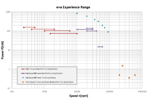
Applications & Power Range
- - Generators for Energy-Recovery-Systems
- Compressor/Chiller/Blower
- Motor elements for the machine tool industry
RPS rotor position measuring device
- The rotor position measuring device ensures that the
same commutation angle is always produced with spindles of the same
construction type during the installation of the e+a synchronous rotor. This
dispenses with the need for individual programming of the commutation angle
at the frequency inverter. When a spindle is replaced the drive can be
monitored at all times and is therefore protected from being damaged beyond
repair.
The motor must be mechanically driven in order to carry out a measurement. The measured values are easily read out using the RS232 interface in conjunction with measurement report software. 
RPS rotor position measuring device
- Measured values
Speed, voltage constant, voltage (phase-phase), mechanical angle, electrical angle, number of poles, number of sensor teeth
Cable connections
Motor phase U, V, W; sensor: 5VDC, 1VSS, A/B/R; serial interface RS232
Options
Sensor cable, case
High Speed Motors
- This website gives a short overview of electrical
machines used as high speed motors and generators, their advantages and some
application fields. Furthermore, the challenges of developing and
manufacturing high speed motors and generators are explained. With e+a
located in Switzerland, there is a competent partner with more than 28 years
of experience in designing and producing customized asynchronous and
synchronous high speed motor elements for various application areas.
Introduction
Various requirements are actually leading to a growing demand for high speed motors. First of all, the continuous need for an increased power density. Due to the quasi linear relation between rotational speed and shaft power of an electrical machine, increasing the rated speed is an effective way to boost power density and efficiency. Hence this approach takes advantage of increasing shaft power without changing the size of the machine. On the other hand, the same performance can be provided in a smaller volume. The latter is paramount in the field of machine tool applications for example. Thus spindles or the machine tool in a whole become smaller, weight is reduced and dynamical behavior is enhanced. Another point in this industry is the cycle time that a machine tool needs to complete a specific operation. The faster a tool can be moved and rotated the faster it is able to complete its task, not taking into account that high speed cutting operation rely on top speed to machine time efficiently respective parts.
Further interesting operation fields of high speed motors are applications where a standard gearbox is used to translate the rotational speed of conventional power grid frequency (50/60 Hz) driven motors to higher speed levels. A replacement of this gearbox and the related conventional motor with a speed controlled drive consisting of a high speed motor and a rectifier increases the overall efficiency and reduces the maintenance significantly.
The compressor industry is an example, where high efficiency, oil-free operation and no emissions make electric high speed motors the most environmental friendly compressor drives. In the context of emission free application energy storage systems with high speed flywheels not only take advantage of high speed generators. Thus fossil generators with unwanted emissions can be avoided and maintenance costs can be reduced significantly. Cryo applications actually experience a very similar revolution of its drive technology. Directly driven motor elements replace a set of a gear box and a 50/60Hz standard motor. Efficiency can be increased, the needed space is by far downsized and maintenance costs are reduced. Hence energy recovery systems e.g. become more and more interesting from a financial and an ecological point of view. Thus high speed motor elements contribute partly to the ongoing development of green energy applications.
Challenges
The mentioned advantage of high speed motors can only be achieved by using high quality motor elements. The reason for that is that due to the high rotational speeds, the centrifugal forces on the rotating motor part (rotor) can be very high leading the materials to the edge of mechanical stress resistivity. Failures in motor elements can result in crashes affecting the environment or at least damage the spindle, where the motor is built in. To prevent this, various physical aspects need to be calculated in a challenging development process, taking electromagnetic, thermal, mechanical stress and structure dynamic aspects into account. The applied computational methods need to be combined with a long experience, to extend actual operation limitations with keeping safety in mind as highest priority. Furthermore, the interaction of the rectifier and the high speed motor needs to be known, because the rectifier has a deep impact on heating, noise, clogging, and power consumption of the machine. Especially the interaction of various converter systems with a high speed motor element demands very specific knowledge and experience. Hence tests of above described applications are crucial to succeed. They require an intense relation between the power electronic and high speed motor specialists. Furthermore the infrastructure enabling performance tests are highly complex and usually not available on the market. Very often the related costs exceed by far the costs incurred during the whole development process of a new motor element product line.
Inverter
Typical inverters are working on base of the pulse wide modulation method, where a continuous switching of voltage or current controls the output waveform. Due to the need for faster high speed motors, the switching frequency increases as well (in modern inverters, IGBT's are used). Although noise and efficiency improve as the number of pulses increase, the inverter leads also to a few drawbacks, especially because of fast switching transients which can be understood as a significant source of stray losses. Additional time harmonics caused by a switching mode inverter has a negative impact on the air gap flux distribution. These harmonics cause additional eddy current losses in the motor elements especially in the rotor, which lead to higher temperatures and a possible degrade of the mechanical behavior. The switching frequency has another impact on the high speed motor, namely on the insulation, which is severely stressed by the repetition and the steepness of the pulse wave front. When IGBTs are used, the high rate of voltage rise of typically 0 - 650 V in less than 0.1 µs leads to approximately 10,000 V/µs. This fact results in adverse effects on the motor insulation. These steep rising and falling pulses lead to an uneven distribution of voltages within the motor, especially during switching transitions. Without a deep knowledge of the motor insulation system and the inverter itself an insulation deterioration and subsequent failure of the motor can occur. In this context partial discharge effects and rotor over heating are well known failure sources. The latter can lead to an unwanted carbon fiber burst due to thermal a mechanical stress in the respective resin carbon fiber compound (synchronous machines).
Conclusion
Asynchronous and synchronous high speed motors offer several advantages like decreased installation space for higher power and unnecessary gearboxes. These advantages apply for several fields and are intensively used in the machine tool, compressor, cryo and energy generating industry for example. Designing and producing these asynchronous and synchronous high speed motors is an exciting task, where the usage of most modern computational methods for the development process is as important as a wide range of experience and expertise to extend actual operation limitations in a safe way. Not only the knowledge of high speed motors is necessary but also a deep inside in inverter technology, partial discharge phenomenon and so called stray or additional losses.
e+a in Switzerland offers a wide product portfolio of high speed motors or generators respectively. With more than 28 years of experience and more than 150,000 different high speed induction machines and permanent magnet synchronous machines running, e+a is one of the world leaders in developing and manufacturing highly customized high speed motors. Furthermore, a professional equipped test bench with all the newest inverters and a partial discharge test system allows detailed analysis and adaptation of rectifier and motor and a very well support for system integrators.
Research
- The development of our high-performance drive starts
at the research. We develop our products on an ongoing basis together with
our customers, internationally renowned universities and technical colleges.
We ensure that the essential skills required to develop and manufacture the
product are available as a one-stop service – from e+a.
We carry out fundamental research to ensure that our highly dynamic drives can withstand the extremely high loads to which they are subjected. A thorough knowledge of materials and a wide-ranging basic knowledge on the calculation of electric rotating machines are equally decisive factors.
We offer young engineers further training and participate in international projects. In this way we not only stay in touch with the latest developments, we also considerably influence developments in our industry.
Swiss precision
- We aim to meet the highest of quality expectations. We
only use high-quality materials and semi-finished products and check each
one of our motor elements several times before it leaves our plant. This is
why e+a motor elements are guaranteed to run every time without fail.
Solid workmanship
Fully-automatic tests, state-of-the-art measuring and testing equipment and a maximum number of testing parameters ensure problem-free functioning of our motor elements. We document our measurements comprehensively and can make the test report available if requested. Our products are carefully packed and reach our customers safely – even on the other side of the world.
Our exclusive partner Kaufmann AG produces the motor elements we develop in modern manufacturing facilities. Traditional manufacturing methods and innovative technology are effectively combined at our production facility to achieve an efficient and flexible manufacturing process. Finished motor elements are also available. From prototype to individual item through to series products: e+a motor elements are renowned throughout the world for their cutting-edge technology and first-class quality.