Navigation : EXPO21XX > ROBOTICS 21XX >
H21: Humanoid and Androids Research
> The University of Western Australia
The University of Western Australia

Videos
Loading the player ...
- Offer Profile
Welcome to the Robotics and Automation Laboratory at the University of Western Australia, Perth. The Lab has been active for over a decade doing research on all types of autonomous mobile robots, including intelligent driving and walking robots, autonomous underwater vehicles, and unmanned aerial vehicles. We also work on the design of embedded controllers and embedded operating systems, as well as on simulation systems.
Product Portfolio
EyeBot Embedded controller for and robotics applications, digital camera, sensors, motor drivers
- EyeBot is a controller for mobile robots with wheels,
walking robots or flying robots. It consists of a powerful 32-Bit
microcontroller board with a graphics display and a digital grayscale or
color camera. The camera is directly connected to the robot board (no frame
grabber). This allows to write powerful robot control programs without a big
and heavy computer system and without having to sacrifice vision - the most
important sensor.
Features:- Ideal basis for programming of real time image processing
- Integrated digital color camera
- Large graphics display (LCD)
- Can be extended with own mechanics and sensors to full mobile robot
- Programmed from IBM-PC or Unix workstation,
- Programs are downloaded via serial line (RS-232) into RAM or Flash-ROM
- Programming in C or assembly language
- Third generation hardware
Driving Autonomous driving robots, differential drive, EyeBot controller, digital camera, infrared
Eve
- Eve (EyeBot Vehicle) was the first driving robot we build
around a specialized EyeBot controller and a QuickCam camera system. This
robot has the standard top part of the EyeBot M1 controller, but a modified
bottom board that matches the outline of the physical robot. We later
discarded this technique for a standard controller (M3) that is identical
for all robot vehicles.
Eve is equipped with:
2 DC motors with encapsulated gears and encoders
1 Infra-red PSD sensor
6 Infra-red proximity sensors
Acoustic bumper system
QuickCam digital camera
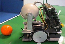
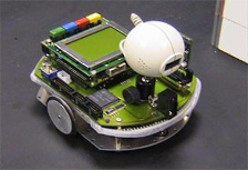
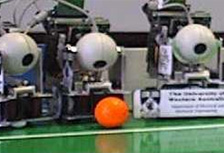
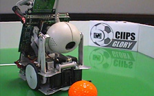
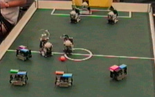
Robot Soccer
- Our next driving robot designs were a number of
variations for the CIIPS Glory Robot Soccer Team. These robots had to be
somewhat smaller than Eve, in order to qualify for the RoboCup competition,
where we entered the 1998 regional contest in Singapore. The original CIIPS
Glory player was equipped with a Color QuickCam camera, which was replaced
in later versions by our own EyeCam design. CIIPS Glory robots have competed
in a number of RoboCup and FIRA World Cup robot soccer events.
We used two servos in addition to the two DC driving motors. These were used for:
Moving the camera
Kicking the ball
Robot Soccer Team
- The original camera movement was a tilt action, which
allowed us to keep the ball in the (relatively narrow) field of view, when
closing in on the ball. We changed this on later robots in favour of a
panning movement, which allows faster tracking of a moving ball without
having to move the whole robot, or a combination of both.
The goal keepers were a variation of the field player design. Since they needed to move primarily sideways instead of forward/backward, re mounted the goal keeper's top plate at a 90 degree angle to the bottom plate and equipped it with a larger ball kicking plate, as lined out in the RoboCup rules.
Omni--direcional Vehicles Mecanum-wheel design, omni-directional robots, EyeBot controller
- Omni-directional vehicles have a significant advantage
over conventional vehicles with car-like Ackermann steering or the
differential drive using two independent wheel motors as in Eve and many of
our driving robots. Omni-directional driving allows going forward/backward,
but also sideways left/right and turning on the spot. This is especially
helpful when having to maneuver in a tight environment such as a factory
floor.
The EyeBot controller drives 4 independent wheels on the omnidirectional robots Omni-1, Omni-2 and Omni-3. These robots use the "Mecanum" wheel design with free rollers around the wheel circumference. Each robot can drive in any direction, i.e. forward/backward, sideways, at an angle, and turn on the spot. The robots are using the EyeBot controller with an add-on module with two additional drivers. 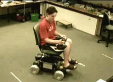
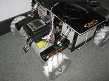
Omni-Wheelchair
- This uses the conventional Mecanum wheel used in Omni-1, and the suspension system in Omni-2, to create a large scale omni-directional robot that is used as a wheelchair.
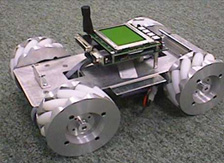
Omni-1
- The conventional Mecanum wheel design with the rollers held at the sides. This is a disadvantage when driving on non-smooth surfaces, because the rims will make contact with the surface.
Omni-2
- A new Mecanum wheel design where the rollers are held in the middle. This gives an advantage when driving on general surfaces, together with a suspension system that suspends every wheel individually.
Omni-Wheelchair with Driver-Assistance System Wheelchair with Mecanum wheel omni-directional drive system, sensor-based driver assistance system for handicapped drivers
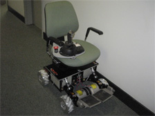
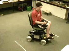
- Design Objectives:
- Semi-autonomous omni-directional wheelchair
- Footprint size about 1m x 1m, with payload about 100kg
- Rimmed Mecanum wheel version
- Independent suspension on all four wheels
Tracked Tracked driving robots for terrain navigation, Eyebot controller, attitude and inertial sensors
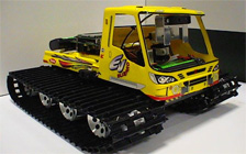
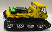
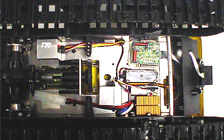
- The EyeTrack vehicle is a modified model car using
tracks for locomotion. We are using an EyeBot controller for driving the
vehicle and reading its sensor data. Since this robot is to be able to
navigate in terrain, we use a number of orientation sensors to avoid going
up or down too steep inclines. The camera is mounted in an active cardanic
fashion using three servos for three axes.
One of the projects involving EyeTrack is an "intelligent remote control". The robot drives under remote control and returns images and other sensor data. However the robot adapts its speed automatically to environment conditions and refuses to execute any commands that could result in the robot getting stuck or falling over. This system could be very useful for a number of rescue or bomb defusing scenarios.
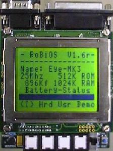
Robot Soccer Small size robot soccer team in RoboCup and FIRA WorldCup competitions, EyeBot controller
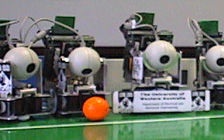
- Our team which has its "home" in the UWA mobile robot
lab was named after the new and successful Perth Glory soccer team. The
heart of the robots are the the EyeBot controllers, developed by a team
around Thomas Braunl. We use a Motorola 68332 32-bit controller, which offer
a variety of digital/analog I/O facilities. We developed our own operating
system RoBIOS for the systems, which allows a great deal of flexibility.
I.e. the same EyeBot system is also used for 6-legged and biped walking
machines, and - as a boxed version - for undergraduate courses in assembly
language.
We incorporated a digital color camera and a graphics display. All image processing is done on-board. Our robots have local intelligence and are not simple pawns, directed by a central system with global vision. Although our approach is clearly disadvanted in respect of winning a RoboCup competition, we are more interested in research on general purpose intelligent agents, as opposed to building a system which serves only a certain competition and has to rely on global sensors.
Each robot has shaft encoders and infrared range sensors in addition to a digital color camera. We are currently incorporating wireless transmissions to allow the robots to talk to each other plus a ball kicking device. We are able to operate even without communication betwen the robots. Each robot will be told its starting position and will use its shaft encoders to keep track of its current position. However, communication will allow much more sophisticated behaviours like passing a ball to another robot.
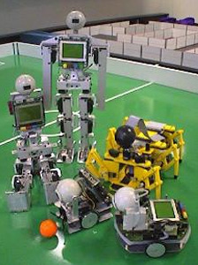
Android Biped Biped walking android robots, several generations with different actuator and sensor equipment
- The mechanics and sensor electronics has been individually constructed around the EyeBot controller. All robots are about 50cm tall and use different sensors for attitude control and balance.
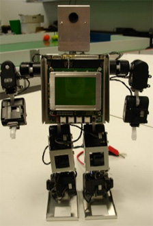
Andy Droid 2
- The Andy Droid robots have been designed by Joker Robotics, however, we have modified Andy1's feet with three toes containing strain gauges as the robot's main orientation sensors. With these, Andy can always determine the center of pressure in each foot and therefore knows its "zero moment point" (ZMP), which allows it to counteract any rotational forces for balancing. Andy2 has an almost identical leg design. Andy2 uses a new digital servo development instead of Andy1's conventional analog servos. These digital servos give feedback via a serial interface and can therefore double as actuators and sensors.
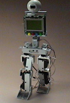
Johnny Walker
- Johnny and Jack were the first two android robots we
designed using relatively inexpensive servos as actuators and testing a
variety of different sensors. A major problem with these robots are the
total weight of the mechanics, electronics, motors and batteries, and the
rather limited torque being supplied by the motors. Any biped robot that has
difficulties balancing on one leg, will have difficulties to perform a
proper walk.
Another major problem is repeatability of a motion. The robots' metal frame structure is quite flexible and tends to swing. Also, the inexpensive servos used have a considerable play and are not capable of an accurate motion repeat. Furthermore, servo performance significantly decreases with ageing of the servos.
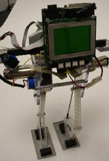
Rock Steady
- With Rock Steady we tried a completely different approach to our first robots Johnny and Jack (see left). This robot should use a minimal number of motors: one motor per leg, plus one motor for sideways balancing of a counterweight. A sophisticated mechanical structure translates the rotaty motion of each leg motor into an articulated leg motion. Instead of servos, we used precision DC motors with encoders for this robot. Inclinometers in two axes are used as orientation sensors for the robot, each motor has an incremental encoder plus an external zero position optical switch.
Balancing Balancing driving robots as studies for biped sensor equipment, Kalman filter
- BallyBot is an experimental balancing robot on two
side-by-side wheels, similar to an inverted pendulum. We are using BallyBot
as an experimental platform to gain insight in sensor system and control
systems to be implemented for humanoid robots.
Two of these experimental robots have been built so far. Bally1 (right) is a simple construction on a single piece of aluminium, holding the controller, sensor, and two Faulhaber motors with wheels.Bally2 (left) is a more compact mechanic design with identical sensors, but motors with a higher gear ratio. The robot is actively balancing and can be driven using IR-Remote input like a remote controlled car. 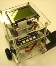
BallyBot 2
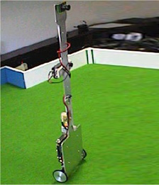
BallyBot 1
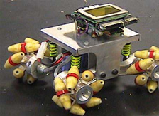
Legged Walking Six-legged walking robots with two dof per leg, various sensor equipment
- Walking robots are often slower than driving robots,
but they have the improtant advantage that they navigate over terrain, while
driving robots require a more or less flat surface. The simplest case of a
walking robot uses 6 legs, sinve this allows to implement a gait that always
lifts up and repositions 3 legs, while the other 3 legs remain on the
ground, providing a solid balance. Such a robot does not need to actively
balance, as is required for our balancing and biped walking (android)
robots. For details see the book "Embedded Robotics".
The mechanics and sensor electronics has been individually constructed around the EyeBot controller.- 12 servos driven by EyeBot
- 2 infra-red PSD sensors
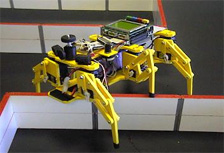
Walking Robots
- mechanics 2nd generation (left) from Lynxmotion
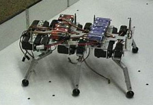
Walking Robots
- mechanics 1st generation (right) developed at Univ. Stuttgart
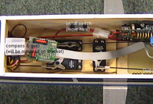
Planes UAV Autonomous planes / Unmanned aerial vehicles, embedded controller with GPS and digital compass
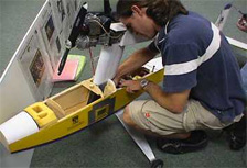
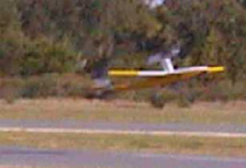
- For our autonomous plane, we use an EyeBot controller
together with a number of sensors to autonomously navigate a plane. All
plane actuators are connected to a specially designed switch that allows to
alternate (via remote control) between a standard model plane remote control
and autonomous flying. That way, the critical actions take-off and landing
can be performed manually, while for the flight between it can be switched
to automatic mode. We rely on a GPS as most important sensor. A flight path
can be specified by entering GPS way points that the plane will approach
successively.
Actuators used in the plane:- Switch box that transfers control of all plane servos either to remote control or automatic control
- Standard servos for roll / pitch / yaw / motor speed
- Lights on the fuselage underside to indicate the plane's internal mode (manual / automatic / error)
Sensors used in the plane:
- GPS
- Digital Compass
- Gyroscope
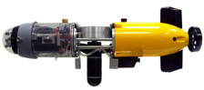
Submarines AUV Autonomous submaries / Autonomous underwater vehicles, embedded controller with inertial sensor system
- Autonomous Underwater Vehicle Projects
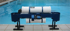
Mako
- AUV with 4 motors, Eyebot, mini-PC, sensor equipment
USAL
- AUV with 2 motors, 1 control surface, Eyebot, sensor equipment

SubSim
- AUV simulation system