
- Offer Profile
NREC automation solutions span a wide range of possibilities, from augmenting a human operator with something akin to "cruise control" to enabling a single human to operate an entire fleet of unmanned vehicles.
From an application standpoint our scope is similarly broad, ranging from huge automated mining machines to tiny robotic repair machines for pressurized gas pipelines.
Operator Assist Technologies
UPI Teleoperation System
- OVERVIEW
NREC has developed an immersive teleoperation system that allows operators to remotely drive an unmanned ground vehicle (UGV) more effectively over complex terrain.
The United States Army’s Future Combat Systems (FCS) program is developing autonomous UGVs for use in military missions. These missions are classic examples of "triple D” – dirty, dull and dangerous. Automating them will save lives and allow the Army to better carry out its essential tasks. However, full robotic autonomy is not yet at the point where it can be used on the battlefield. Human intervention is still necessary to successfully make use of UGVs under real-world conditions.
Teleoperation allows a human operator to remotely control a UGV. During tactical missions, UGV must maneuver at high speeds and may range far from the operator. The poor situational awareness that current teleoperation systems provide makes it nearly impossible to maintain the pace of operations (optempo) needed to successfully perform tactical missions. By developing more effective teleoperation systems, the military can reap the benefits of using unmanned systems without having to wait for breakthroughs in autonomy.
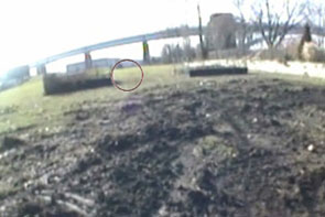
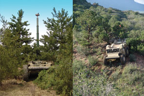
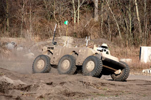
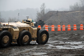
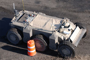
NREC is developing an immersive teleoperation system as part of the UPI program (UGCV-PerceptOR Integration). NREC’s teleoperation system has been tested on the Crusher UGV under a wide variety of driving conditions. This testing has quantified factors that affect a remote operator’s ability to drive quickly and safely in challenging off-road environments.
APPLICATION
The United States Army has set an ambitious goal of having one third of its ground vehicles be unmanned by the year 2015. Recent successes in deploying scouting and bomb disposal robots have demonstrated practical uses for unmanned systems and encouraged their development and deployment for a wider range of tactical missions.
However, the unmanned ground vehicles (UGVs) that have been deployed so far require teleoperation (remote operation by a human being). Despite recent developments in autonomy, autonomous vehicles still require human intervention. Effective teleoperation is therefore crucial to their successful use.
For teleoperation to work, operators need situational awareness of the UGV’s surroundings. Once an operator takes active remote control of a UGV, it can take minutes to assess the vehicle’s environment and decide what to do next. Providing good visual and physical feedback to the operator improves the operator’s situational awareness and allows the UGV to be operated more effectively.
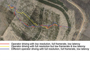
NREC’s immersive teleoperation system makes operators feel as if they’re actually riding in the vehicle. Field tests of the teleoperation system found tradeoffs between operator performance and parameters like bandwidth, latency, field of view, and video frame rate. Identifying key parameters for successful teleoperation allows the operator to make the most efficient use of the limited data bandwidth between the vehicle and the operator control station.DESCRIPTION
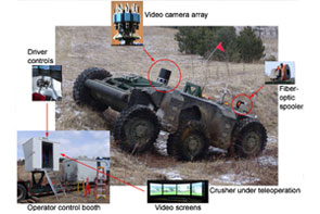
The teleoperation system has four components:- A sensor system mounted on Crusher. It included a high-resolution video camera system and a microphone to pick up sounds in the environment. The camera array consisted of five video cameras, each with a resolution of 1600 x 1200 pixels. These cameras gave the operator a 202 degree by 31 degree field of view.
- A fiber-optic data link between Crusher and the operator station. A kilometer of fiber-optic cable was mounted on a spooler and laid behind the vehicle as it was driven along the test courses. Under ordinary operating conditions, a wireless data link would be used instead of a fiber-optic tether. However, fiber-optic cable was used during testing to provide greater bandwidth.
- A software control system that provided near real-time processing of video images from the camera system. It corrected the video images and controlled their frame rate, resolution, field of view, and other video parameters. It also controlled the operator’s five-screen video display system.
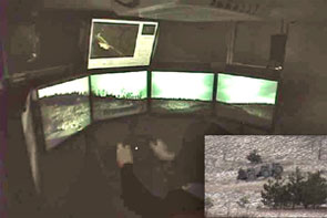
- A control booth that provided visual and vestibular feedback to the driver. Crusher was driven from the operator control booth. Five high-resolution display screens surrounded the driver, each showing an image from one of the vehicle cameras. This gave the driver an immersive, wide angle view of the vehicle’s surroundings. Speakers played noises from the vehicle’s environment. The booth was mounted on a motion base that tracked Crusher’s motion. This gave the driver a physical sense of the vehicle’s movement to complement visual and audio from the vehicle.
Soldier Awareness through Colorized Ranging (SACR)
- OVERVIEW
NREC developed a real-time 3D video system to improve situation awareness in teleoperation and indirect driving.
SACR (Soldier Awareness through Colorized Ranging) fuses video images and ladar in real time to create highly realistic 3D video. Drivers can zoom and pan this wide angle 3D view of the vehicle’s environment. They can shift the virtual camera’s viewpoint to different points around the vehicle – including a synthetic overhead view – to better see its surroundings. Drivers inside vehicles can “see” through the hull. Remote drivers can have a perpetual synthetic line of sight, as if following behind the teleoperated vehicle on foot or in an aircraft. Maps and autonomy plots can be overlaid on the image.
These improvements give drivers a better view of a vehicle’s surroundings, improving their awareness of its environment and making remote and indirect driving safer, easier, and faster. Other potential SACR applications include mapping, mission visualization, mission rehearsal, and localization of personnel and vehicles.
In field trials, operators performed 20% to 50% better on a range of driving tasks with SACR than they did with existing 2D video systems.APPLICATION
Poor situation awareness makes indirect driving (where a driver is sealed inside a windowless vehicle for protection) and remote driving (where a driver teleoperates an unmanned vehicle) more difficult. In both, drivers rely on video cameras that have a limited field of view, display conflicting or confusing images, and cannot show an external view of the vehicle. This limits vehicle speed and contributes to accidents.
Drivers need to know what is going on in the vehicle’s environment and to be able to predict what will happen next. However, this is hard to do without being able to see around the entire vehicle. It can take minutes for a driver to become adequately aware of a teleoperated UGV’s surroundings – time that he or she may not have during a mission!
SACR (Soldier Awareness through Colorized Ranging) uses 3D video to improve a driver’s awareness of the environment. It provides several features that assist indirect and remote driving:- A geometrically correct “virtual driver’s windshield” can be shifted to different points around the vehicle. This makes it easier to view the outside the vehicle and compensates for a driver’s offset from the sensor’s physical location.
- Widening the field of view allows the driver to see more of the vehicle’s surroundings at a glance.
- Drivers can zoom into and out of images to better see points of interest and even “fly around” the outside of the vehicle. An overhead view is especially useful for teleoperating UGVs (similar to driving a radio-controlled toy car).
- Video memory allows the camera to “see through” the vehicle, showing areas that would ordinarily be blocked by parts of the vehicle. This is especially useful for seeing the ground immediately in front of, underneath, or in back of the vehicle – none of which are easily observable from fixed-mount cameras.
- One 3D video feed can produce multiple views for multiple operators.
- Maps, autonomy plots, and other mission-critical information can be superimposed on the 3D video image.
DESCRIPTION
Sensors
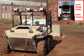
The SACR sensor pod includes a high-definition video camera and laser range finder. One or more sensor pods can be mounted on a vehicle.
3D Video
SACR fuses video and range input from the sensor pods in real time to build a 3D computer graphics model of the vehicle’s surroundings.
Underground Mining Operator Assist
- OVERVIEW
NREC’s Underground Mining Operator Assist project improves safety and increases productivity in the underground mining industry.
NREC applied robotic sensors to the development of semi-automated continuous mining machines and other underground mining equipment. Sensors mounted on the mining equipment can accurately measure the machine's position, orientation and motion. These sensors will assist operators standing at a safe distance to precisely control the machine.APPLICATION
The Problem
The U.S. is a world leader in coal production, but profits are squeezed continually. Utility deregulation presses prices down while smaller and shorter seams limit productivity while increasing the costs of mining. Poor visibility underground limits efficiency, as do requisite safety precautions, which nevertheless fail to prevent accidents, injuries and fatalities.
The Solution
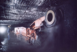
NREC, in collaboration with partners NASA and Joy Mining Machinery, developed robotic systems for semi-automating continuous miners and other equipment used for underground mining.
NREC mounted sensors on a Joy continuous miner to accurately measure the machine’s position, orientation, and motion. These sensors assist operators standing at a safe distance to precisely control the machine. Increases in operating precision increases productivity in underground coal mining and decreases the health and safety hazards to mining workers.DESCRIPTION
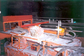
The NREC development team developed two beta systems to improve equipment positioning, including:- A product to measure the sump depth of a continuous mining machine without the use of external infrastructure. This product is useful for matching the volume of cut coal with the capacity of the haulage vehicles and for increasing productivity via faster sequencing of mining operations.
- A global heading measurement product using a laser reference to cut a straight entry. This product helps eliminate trim cuts, reduces extra roof bolts, and increases productivity via accelerated sequencing.
In above-ground tests, the team demonstrated the ability to measure sump depth with no more error than two percent of distance traveled. The team also demonstrated the ability to track the laser reference to within one centimeter lateral offset and 1/3 degree heading error.
Following the above-ground tests, the team conducted underground testing at Cumberland mine in Pennsylvania and Rend Lake mine in Illinois. More extensive underground testing continued as part of a DoE-FETC-funded program that added DoE INEEL and CONSOL as partners.
Vehicle Safeguarding
- OVERVIEW
NREC designed, developed and tested a fully autonomous system capable of following pre-taught paths while detecting and avoiding obstacles.
Being able to detect obstacles and terrain hazards significantly increases the safety of both manned and unmanned agricultural vehicles. The project uses machine learning techniques and sensor fusion to build a robust obstacle detection system that can be easily adapted to different environments and operating conditions.APPLICATION
The Problem
Agricultural equipment is involved in a significant number of accidents each year, often resulting in serious injuries or death. Most of these accidents are due to operator error, and could be prevented if the operator could be warned about hazards in the vehicle’s path or operating environment.
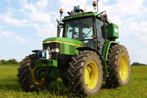
At the same time, full automation is only a few steps away in agriculture. John Deere has had great success in commercializing AutoTrac, a John Deere developed automatic steering system based on GPS positioning. AutoTrac is currently sold as an operator-assist product, and does not have any obstacle detection capabilities. Adding machine awareness provides safeguarding to a product like AutoTrac, for example, that would be a significant enabler to full vehicle automation.
Any perception system that is used for safeguarding in this domain should have a very high probability of detecting hazards and a low false alarm rate that does not significantly impact the productivity of the machine.The Solution
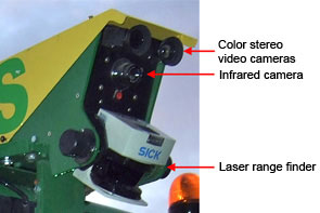
The NREC developed a perception system based on multiple sensing modalities (color, infrared and range data) that can be adapted easily to the different environments and operating conditions to which agricultural equipment is exposed.
We have chosen to detect obstacles and hazards based on color and infrared imagery, together with range data from laser range finders. These sensing modalities are complementary and have different failure modes. By fusing the information produced by all the sensors, the robustness of the overall system is significantly improved beyond the capabilities of individual perception sensors.
An important design choice was to embed modern machine learning techniques in several modules of our perception system. This makes it possible to quickly adapt the system to new environments and new types of operations, which is important for the environmental complexity of the agricultural domain.DESCRIPTION
In order to achieve the high degree of reliability required of the perception system, we have chosen our sensors so that they provide complementary information that can be exploited by our higher level reasoning systems. To correctly fuse information from the cameras, the laser range finders and the position estimation system we have developed precise multi-sensor calibration and time synchronization procedures.
We implemented feature extractors that analyze the images in real time and extract color, texture and infrared information that is combined with the range estimates from the laser in order to build accurate maps of the operating environment of the system.
Since our perception system had to be easily adaptable to new environments and operating conditions, hard coded rule-based systems were not applicable to the obstacle detection problems we were analyzing. As a result, we developed machine learning for classifying the area around the vehicle in several different classes of interest such as obstacle vs. non-obstacle or solid vs. compressible. Novel algorithms were developed for incorporating smoothness constraints in the process of estimating the height of the weight supporting surface in the presence of vegetation, and for efficiently training our learning algorithms from very large data sets.
The initial system, installed on the 6410 John Deere tractor, has been demonstrated in several field tests. We are currently focusing on a small stand-alone perception system that uses cheaper sensors and could potentially by used as an add-on module for several existing types of agricultural machinery.
Vehicle Stability Prediction
- OVERVIEW
NREC has developed an easy-to-implement solution to an important problem — stability margin estimation as it relates to vehicular rollover and tipover vulnerabilities.
A concrete realization of a stability margin estimation system for real-world applications has not existed until now. NREC scientists and engineers developed a real-world, effective system to prevent maneuver-induced rollover and tipover.
NREC’s Stability Prediction System (SPS) calculates the effects of lateral acceleration and gravity as either curvature, speed, or slope increase, and when state of motion approaches a tipover condition, the system recognizes the situation and stabilizes the vehicle.APPLICATION
The Problem
For vehicles operating on slopes, the inherently "reduced stability margin” significantly increases the likelihood of rollover or tipover.
Unmanned ground vehicles (UGVs) are not the only wheeled vehicles that traverse rough terrain and steep slopes. Contemporary, driver-operated mining, forestry, agriculture and military vehicles do so, as well, and frequently at high speeds over extended periods of time. Cranes, excavators and other machines that lift heavy loads also are subject to dramatically increased instability when operating on slopes. Slopes are only one factor to consider. Preventing vehicular tipover on flat surfaces (inside a warehouse, for example) is just as important, especially when considering that market forces reward manufacturers of lift trucks that are smaller, lift heavier loads and lift those loads higher than could be done previously.
The Solution
NREC experts devised a solution featuring a combination of sophisticated software and hardware, including inertial sensors and an inclinometer-type pendulum at the vehicle’s center of gravity.
During vehicular operation, the system continuously and actively calculates stability margin measurements to trigger an alarm, drive a "governor” device or alter the suspension. It calculates lateral acceleration as either curvature or speed increase. When state-of-motion activity reaches rollover / tipover vulnerability, the system recognizes the situation and triggers the desired action.
This system can be deployed on robotic and driver-operated vehicles (including cars) and machinery (cranes, excavators, lift trucks, pallet jacks, etc.).DESCRIPTION
NREC researchers developed algorithms for a stability margin estimation system. These algorithms take into account diverse variables such as the aggregate effect of gravity and changing kinematic forces. NREC scientists then developed animated simulations to test models for maneuver-based stability of vehicles and machinery (lift trucks, excavators, cranes, etc.) at various slopes, speeds and payload articulations.
Further testing involved the use of test-bed hardware, including a lift truck. The lift truck underwent major retrofitting to incorporate sensors, (gyro, axis accelerometer and inclinometer), stabilizing equipment, computer hardware and control software. As part of the hardware platform, NREC created a data logger system for use in simulation scenarios. NREC testers calibrated the models used in simulation to minimize risk of tipover of the actual test vehicles.
The sensing/driver control system was developed in Matlab/Simulink and included models for inertial sensors and a user interface to simulate input driver commands to the lift truck, including steer, speed, lift height, side-shift and tilt. Furthermore, a software interface layer was defined to connect the stability-prediction algorithms to the sensing system. Through the driver control interface, the user can input drive commands to the truck, which results in the dynamic model responding to these commands. As the vehicle executes the user commands, the sensing system monitors vehicle stability.
Autonomous Vehicle Technologies
UGCV PerceptOR Integration (UPI)
- OVERVIEW
The UPI program builds upon the success of UGCV and PerceptOR to improve the speed, reliability, and autonomy of unmanned ground vehicles.
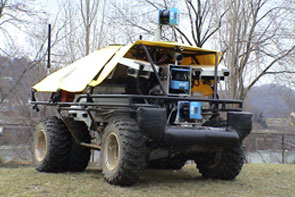
UPI combines the mobility and ruggedness of the Crusher vehicles with advanced perception, autonomy and learning techniques. The program stresses system design across vehicles, sensors and software, so that each component’s strengths compensates for another’s weakness.
As a Future Combat Systems (FCS) technology feed program, the UPI program’s results are advancing work on other autonomous vehicle programs including the Armed Reconnaissance Vehicle (ARV) and the Autonomous Navigation System. (ANS).APPLICATION
The Problem
Navigating complex terrain at speed and with minimal human supervision has always been a major challenge for UGVs. The need to recognize obstacles requires a dramatic improvement in perception capability. Also, the continued likelihood of running into obstacles requires a vehicle that is rugged enough to continue operating after sustaining tolerable damage in collisions.
The Solution
Building on successful results from PerceptOR, the UPI program’s perception and automation systems are being extended to improve automation capabilities at higher speeds.
As part of UPI, NREC designed a new vehicle, Crusher, which features a new highly durable hull, increased travel suspensions, and leverage off many development and improvements from the Spinner vehicle.
Enhanced perception capabilities include new "learning” technologies that enable the vehicle to learn from terrain data. It can then navigate new, highly varied terrains with increasing levels of autonomy. The team is also applying machine learning techniques to improve Crusher ’s localization estimate in the absence of GPS.
Payload development, integration and testing are scheduled to continue through 2008. UPI will bring together technologies and people to produce autonomous vehicle platforms capable of conducting missions with minimal intervention.DESCRIPTION
With the addition of two new vehicles, the program will be able to conduct three parallel field testing agendas in varied terrain sites:- Building on successful results from PerceptOR, the perception and automation systems will be extended to provide improved automation capabilities at higher speeds. Increased focus will be placed on the use of prior overhead data as well as learning technologies which will allow the vehicle to move effectively through previously untraveled terrains. Technologies that can supervise or support off-road navigation in highly varying terrain will be a priority.
- Vehicle field testing will continue, allowing for continuous improvement of obstacle capability, resilience, endurance, and payload fraction (key goals for UGVs). Vehicle performance will be analyzed, modified, and tested continuously to maximize the inherent terrainability of the Crusher platform.
- Payload development, integration and testing will prove out the intended mission scenarios. Leveraging upon unmanned vehicle capabilities and Crusner's unique terrain capabilities, these field tests will help demonstrate and influence the use of autonomous vehicles in the future.
Urban Challenge
- OVERVIEW
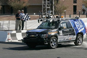
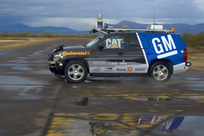
Carnegie Mellon University and General Motors built an autonomous SUV that won first place in the 2007 DARPA Urban Challenge.
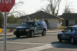
The Urban Challenge race was held on November 3, 2007 at the Victorville training facility in California. Eleven teams competed against each other to finish a 60-mile city course in less than six hours. Their vehicles had to conduct simulated missions in a mock urban area while obeying traffic laws, safely merging into moving traffic, navigating traffic circles, negotiating busy intersections, and avoiding other vehicles – all without human intervention.
Carnegie Mellon’s “Boss” (an autonomous Chevy Tahoe named after legendary General Motors engineer Charles “Boss” Kettering) was the first of three vehicles that actually finished the race within the six-hour time limit. Three other entries finished after the time limit had expired.
Carnegie Mellon’s Tartan Racing team was led by internationally-recognized mobile robotics expert Red Whittaker and key members of Red Team Racing, who fielded strong entries in the 2004 and 2005 DARPA Grand Challenge races. Faculty and staff from across the university, including Tony Stentz, Alonzo Kelly and Drew Bagnell from the National Robotics Engineering Center, joined Tartan Racing’s drive to win the Urban Challenge. General Motors, Caterpillar, Continental and other partners brought their vehicle development and engineering expertise to the Urban Challenge.APPLICATION
The 60-mile Urban Challenge course wound through an urban area with crowded streets, buildings, traffic, road signs, lane markers, and stop lights. The exact route was unknown until the morning of the race. Each vehicle attempted to complete a series of three missions within a six-hour time limit. No human intervention whatsoever was allowed during the race. Each vehicle used its on-board sensing and reasoning capabilities to drive safely in traffic, plan routes through busy streets, negotiate intersections and traffic circles, obey speed limits and other traffic laws, and avoid stationary and moving obstacles – including other Urban Challenge competitors.
Tartan Racing entered the Urban Challenge to bring intelligent autonomous driving from the pages of science fiction to the streets of your town. The technologies developed for this race will lay the groundwork for safer, more efficient, and more accessible transportation for everyone.
An aging population and infrastructure and rising traffic volumes put motorists at risk. Without technological innovation, auto accidents will become the third-leading cause of death by 2020. Integrated, autonomous driver assistance systems and related safety technologies will prevent accidents and injuries and save lives. They will also help people retain their freedom of movement and independence as they grow older.
Autonomous driving technologies can also be used to improve workplace safety and productivity. Assistance systems for heavy machinery and trucks will allow them to operate more efficiently and with less risk to drivers and bystanders.DESCRIPTION
Tartan Racing took a multi-pronged approach to the daunting challenge of navigating the dynamic environment of a city:- Organize and orchestrate concurrent software components to determine
sequences of tasks, process sensor data, and control the vehicle.
Response times had to be less than a second! Other software components
continuously monitored the status of individual tasks to find out
whether they were
successfully completed. - Sense, differentiate and localize objects (such as buildings and cars) and environmental features (such as lane markings, curbs, and sidewalks), both fixed and moving. The vehicle used radar, ladar, and video sensors to perceive its environment and GPS and IMUs to establish its position.
- Control actuators to ensure safe and efficient driving in intersections, parking lots, traffic circles, and similar city features.
- Plan and replan the most efficient routes through a network of streets, taking into account constantly-changing conditions.
- Retrofit two stock Chevy Tahoe SUVs to enable computer control of their steering, speed and gears.
- Achieve robustness by applying well-known principles of systems engineering and testing, using both simulation and live tests. The goal was to make the vehicles as reliable as possible for the race.
NREC faculty and staff took on key leadership roles in conquering these technical challenges.
- Organize and orchestrate concurrent software components to determine
sequences of tasks, process sensor data, and control the vehicle.
Response times had to be less than a second! Other software components
continuously monitored the status of individual tasks to find out
whether they were
Automated Material Transport System
- OVERVIEW
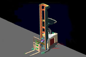
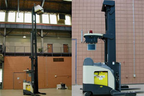
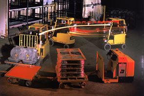
NREC developed AMTS, an innovative system for accurately guiding robotic material transport vehicles in industrial settings.
AMTS uses robotic lift trucks to automate the transfer of pallets and other materials from semi-trailers onto robotic tugs for transport in factories and warehouses. It makes use of a sophisticated downward computer vision system and LADAR range finders to direct and control these vehicles as they load and unload material and transport it across the factory floor.
AMTS’s lower-cost, infrastructure-free automation system decreases human involvement in setting up and operating material transport systems. It makes automated loading and unloading of over-the-road trailers more feasible and cost-effective.APPLICATION
The Problem
Until the scientists and engineers at NREC developed the AMTS solution, companies had limited options to relying on driver-operated forklifts and tug vehicles for transporting materials and stacking pallets in factories and warehouses.
Current automated guided vehicles (AGVs) are limited by their inability to "see” their surroundings. And, in order to function at all, they required complex setup and costly changes to facility infrastructure. For example, companies using conventional AGVs have to install special sensors, jigs and attachments for an automated forklift to pick up a pallet of materials.
The Solution
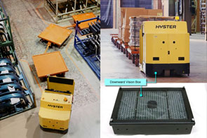
NREC scientists and engineers devised a computer vision system that can be used with any mobile robot application. Today’s cost-effective AMTS solution works effectively around the clock, with lights out in many cases and with less damage to vehicles than humans cause. There is typically no need to retrofit the facility infrastructure to accommodate the AGVs. These AMTS-equipped automated vehicles — robotic forklifts and tugs — find their way around by virtue of a low-cost, high-speed positioning system developed at NREC.
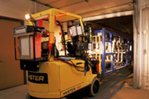
NREC equips each vehicle with a combination of cameras and laser rangefinders for navigation and control. With a downward-looking camera mounted to the bottom of the forklift, the robot captures visual cues and matches them to a pre-stored database of floor imagery that becomes its map for navigating the floor.
Using a forward-looking camera system, the forklift images the side of the trailer to find pallets for transfer to tug vehicle wagons. The forks are inserted into the pallet holes, and the forklift lifts the pallet. While it is backing out of the trailer, the robotic forklift relies on its laser rangefinder to safety remove the tight-fitting pallet from the trailer. The robotic tug vehicle uses the same downward vision technology to move around and position its wagons for loading and unloading.DESCRIPTION
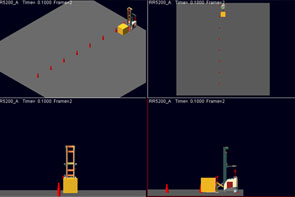
NREC scientists and engineers developed four novel vision systems and associated visual servoing control systems, as well as factory-level vehicle traffic coordination software.
Development of the AMTS solution began with prototypes of both the position-estimation technology and pallet-acquisition vision system. After integrating NASA technology into these systems, NREC provided a demonstration of simplified, automated trailer loading/unloading and automated pallet stacking.
Subsequently, during an AGV pilot program at an automotive assembly plant, several tug AGVs used the AMTS downward vision technology and proved its viability.
Today, the AMTS is available as a pragmatic solution for efficient, cost-effective materials transport in manufacturing facilities, industrial plants and storage warehouses. Because it requires no changes to facility infrastructure, it makes automated materials handling more practical and affordable than ever before.
Black Knight
- OVERVIEW
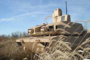
The National Robotics Engineering Center (NREC) developed sensing, teleoperation and autonomy packages for BAE Systems' Black Knight, a prototype unmanned ground combat vehicle (UGCV).
Black Knight demonstrates how UGCVs can be used in the field and showcases current robotics technologies. NREC applied its expertise in sensor fusion, unmanned systems, obstacle detection, path planning, autonomy and teleoperation to improve Black Knight's mission performance and support Soldier operation.APPLICATION
Black Knight can be used day or night for missions that are too risky for a manned ground vehicle (including forward scouting, reconnaissance surveillance and target acquisition, (RSTA), intelligence gathering, and investigating hazardous areas) and can be integrated with existing manned and unmanned systems. It enables operators to acquire situational data from unmanned forward positions and verify mission plans by using map data to confirm terrain assumptions.
Black Knight demonstrates the advanced capabilities that are available to unmanned ground combat vehicles (UGCVs) using current technology. Its 300 hp diesel engine gives it the power to reach speeds of up to 48 mph, with off-road autonomous and teleoperation speeds up to 15 mph. Its band-tracked drive makes it highly mobile in extreme off-road terrain while reducing its acoustic and thermal signatures. The 12-ton Black Knight can be transported within a C-130 cargo plane and makes extensive use of components from the Bradley Combat Systems program to reduce costs and simplify maintenance.
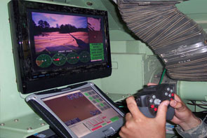
Black Knight can be teleoperated from within another vehicle (for example, from the commander's station of a Bradley Fighting Vehicle) or by dismounted Soldiers. Its Robotic Operator Control Station (ROCS) provides an easy-to-use interface for teleoperating the vehicle. Black Knight's autonomous and semi-autonomous capabilities help its operators to plan efficient paths, avoid obstacles and terrain hazards, and navigate from waypoint to waypoint. Assisted teleoperation combines human driving with autonomous safeguarding.
Black Knight was extensively tested both off-road and on-road in the Air Assault Expeditionary Force (AAEF) Spiral D field exercises in 2007, where it successfully performed forward observation missions and other tasks. Black Knight gave Soldiers a major advantage during both day and night operations. The vehicle did not miss a single day of operation in over 200 hours of constant usage.DESCRIPTION
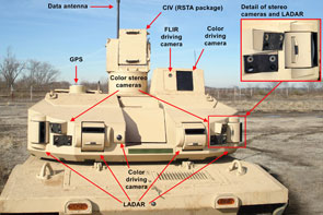
NREC developed Black Knight's vehicle controller, tele-operation, perception and safety systems.
Black Knight's perception and control module includes Laser Radar (LADAR), high-sensitivity stereo video cameras, FLIR thermal imaging camera, and GPS. With its wireless data link, the sensor suite supports both fully-autonomous and assisted (or semi-autonomous) driving.
Black Knight's autonomous navigation features include fully-automated route planning and mission planning capabilities. It can plan routes between waypoints – either direct, straight-line paths or paths with the lowest terrain cost (that is, the lowest risk to the vehicle). Black Knight's perception system fuses LADAR range data and camera images to detect both positive and negative obstacles in its surroundings, enabling its autonomous navigation system to avoid them.
These autonomy capabilities can also assist Black Knight's driver during teleoperation. Black Knight can plan paths to be manually driven by its operator. In “guarded teleoperation” mode, objects that are detected by the perception system are overlaid on the driving map, enabling drivers to maneuver around them. The vehicle also stops when it detects lethal obstacles in its path. Black Knight is driven from the Robotic Operator Control Station (ROCS), located within another vehicle. It can also be driven off-board via its safety controller. The ROCS displays images from the vehicle's color and FLIR driving cameras and includes a hand controller for steering the vehicle and operating its sensors. It also allows the driver to control and view the status of the various vehicle and sensor systems. Map and route displays help the driver to navigate through unfamiliar terrain.
The ROCS also allows operators to control the Commander's Independent View (CIV) sensor suite. The CIV is used for remote surveillance and target acquisition (RSTA) and includes color video and FLIR cameras.
Autonomous Loading System
- OVERVIEW
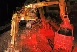
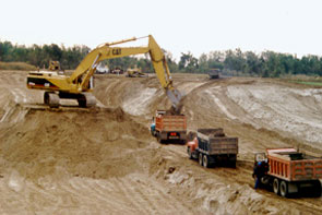
NREC developed ALS, which completely automates the task of loading excavated material onto dump trucks.
The ALS robotic excavator is capable of loading trucks at the speed of an expert human operator, increasing productivity and improving the safety of excavation projects.
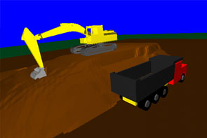
The excavator uses two scanning LADAR rangefinders to locate the truck, measure the soil face and detect obstacles. The ALS software decides where to dig in the soil, where to dump the excavated soil in the truck, and how to quickly move between these points while detecting and stopping for obstacles. The system modifies both its digging and dumping plans based on soil settling detected by its sensors.APPLICATION
The Problem
Surface mining of metals, quarrying of rock, and construction of highways requires the efficient removal of massive quantities of soil, ore, and rock. Human-operated excavators load the material into trucks. Each truckload typically requires several passes, each of which in turn takes 15–20 seconds. The operator’s performance peaks early in the work shift but wears down with fatigue. Scheduled idle times, such as lunch and other breaks, also diminish production across a shift.
Safety is another important consideration. Excavator operators are most likely to be injured when mounting or dismounting the machine. Operators tend to focus on the task at hand and may fail to notice other site personnel or equipment entering the loading zone.The Solution
Automating the excavation and loading process would increase productivity and improve safety by removing the operator from the machine and by providing complete sensor coverage to watch for potential hazards entering the work area.
Recognizing this opportunity, NREC scientists and engineers developed a system that completely automates the truck loading process.DESCRIPTION
In designing the ALS and conducting experimental trials, the ALS team used a combination of hardware, software and algorithms for perception, planning and control.
The ALS hardware subsystem consists of the servo-controlled excavator, on-board computing system, perception sensors and associated electronics. During development of the system, the NREC team developed a laser-based scanning system that would be able to penetrate a reasonable amount of dust and smoke in the air. Additionally, the team developed two different time-of-flight scanning ladar systems that are impervious to ambient dust conditions.
The NREC team designed the software subsystem with several modules to process sensor data, recognize the truck, select digging and dumping locations, move the excavator’s joints, and guard against collision.
Planning and control algorithms decide how to work the dig face, deposit material in the truck, and move the bucket between the two. Perception algorithms process the sensor data and provide information about the work environment to the system’s planning algorithms.
Expert operator knowledge was encoded into templates called scripts, which were adjusted using simple kinematic and dynamic rules to generate very fast machine motions. The system was fully implemented and demonstrated on a 25-ton hydraulic excavator and succeeded in loading trucks at about 80% of the speed of an expert human operator.
LAGR Robot Platform
- OVERVIEW
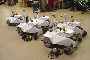
DARPA needed to supply a standard, mobile robot platform to research teams performing on the Learning Applied to Ground Robots (LAGR) program. NREC designed, built and delivered 12 turnkey robots in seven months to support the LAGR kick-off meeting.
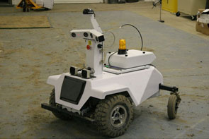
The LAGR robot includes all the necessary hardware, sensing and software for autonomous operation indoors or outdoors. Its well documented application program interface (API) and modular design allows for partial or total swap of the autonomy software modules with the owner’s software.
A developer-friendly design features long battery life, standard development environment, extensive data logging capabilities, and system simulator.
Today, NREC supports more than a dozen customers and 30 fielded robots. NREC provides remote technical support, spare parts supply and user training.APPLICATION
The goal of the LAGR program is to develop a new generation of learned perception and control algorithms that will address the shortcomings of current robotic ground vehicle autonomous navigation systems through an emphasis on learned autonomous navigation. DARPA wanted the ten independent research teams they selected to immediately focus on algorithm development rather than be consumed early in the project with getting a baseline robotic platform working. DARPA also wanted a common platform so that software could be easily shared between teams and so that the government could make an objective evaluation of team results.
In just seven months, NREC designed and then built 12 LAGR robots which allowed DARPA to hold the LAGR kick-off meeting on time and to provide each research team with a fully functional autonomous platform for development.
Teams were given 4 hours of training at kick-off and were able to program basic obstacle avoidance capability the same day. Developers were able to focus immediately on learning algorithm research because all basic autonomy capabilities along with well documented APIs were provided with delivery.
Careful configuration control for all platforms enables developers to develop software at their home station, load their software on a memory stick, and ship the memory stick to DARPA, which then runs the software on their LAGR robot.DESCRIPTION
The LAGR robot includes three 2.0 GHz Pentium-M computers, stereo cameras, IR rangefinders, GPS, IMU, encoders, wireless communications link, and operator control unit. NREC ported its PerceptOR software to the platform to provide baseline autonomous capability.
Communications tools include Gigabit Ethernet for on-board communication; a wireless (802.11b) Ethernet communications link; remote monitoring software that can be run on a laptop; and a standalone radio frequency remote.
The user can log data on the robot in three different modes: teleoperation using the RF remote; teleoperation from the onboard computer system (OCS); and during autonomous operation.
With each robot, NREC ships a comprehensive user manual that documents robot capability, baseline autonomy software, and APIs (with examples) that enable developers to easily interface robot sensor data to their perception and planning algorithms.
Autonomous Spraying
- OVERVIEW
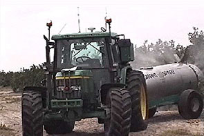
NREC converted a John Deere tractor into an autonomous vehicle for spraying water in orchards.
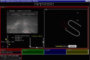
NREC developed a vehicle retrofit kit that allowed the tractor to operate without a human driver. Its software accurately estimated the vehicle’s position and enabled it to autonomously follow previously-driven paths.
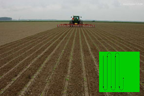
The autonomous tractor sprayed water while following a seven kilometer long path through an orange orchard without any human intervention.APPLICATION
The Problem
Crop spraying is inherently hazardous for the operators that drive spraying equipment. Removing the driver from the machine would lead to increased safety and reductions in health insurance costs. Furthermore, if a system can support nighttime operations less chemical needs to be sprayed for the same effect, due to increased bug activity. This results in higher quality crops and reduced spraying expenses.
The Solution
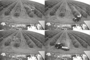
The NREC developed an unmanned tractor that can be used for several agricultural operations, including spraying. The system uses a GPS receiver, wheel encoders, a ground speed radar unit and an inertial measurement unit (IMU) in order to precisely record and track a path through a field or an orchard. The NREC team mounted two color cameras on the vehicle, to enable the use of color and range based obstacle detection.
The teach/playback system was tested in a Florida orange grove, and it sprayed autonomously while following a path of 7km at speeds ranging between 5 and 8 km/h.DESCRIPTION
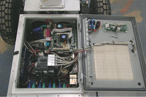
The initial focus of the project was the design of the retrofit kit for converting the 6410 tractor to an autonomous vehicle. One of the key requirements was that after the retrofit the vehicle is still drivable by a human like a normal tractor, in order to facilitate the path recording process. Since the vehicle was not drive-by-wire, the NREC developed actuators for braking, steering and speed control.
To achieve the path teach/playback capability, NREC developed a positioning system that uses an extended Kalman Filter for fusing the odometry, the GPS information and the IMU measurements. The path following system is based on the Pure Pursuit algorithm. More information about the performance of the system can be found in our "Autonomous Robots” paper.
Robotics Simulation Support
- OVERVIEW
NREC is collaborating with RAND Corporation to incorporate NREC’s field-proven robotic mobility and planning software into RAND’s suite of high-resolution, force-on-force simulators.
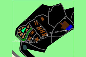
To better analyze scenarios involving robotic systems, NREC and RAND added robotic planning, mobility and control algorithms to high-resolution simulation models. NREC's Field D* dynamic planning library has been incorporated into RAND's Janus and Joint Conflict and Analysis Tactical Simulation (JCATS) force-on-force simulation environments. NREC’s fractal terrain generation algorithms (which generate very high-resolution terrain for robotic mobility simulations) and intervisibility algorithms (which determine whether targets are visible to assets and assets are visible to threats) have also been added to the Janus and JCATS simulators.APPLICATION
Most constructive and virtual simulations have very simplified representations of robotic systems, particularly with respect to mobility, target acquisition, interaction, and collaboration. Military simulation planning algorithms often treat robotic vehicles as manned entities with reduced speeds and sensing capabilities. Models seldom incorporate representations for such aspects as autonomous planning, perception, and coordination. Scenarios for examining future applications of ground and air robotic systems tend to focus on manned system missions, with minimal development of uniquely robotic capabilities.
By connecting field-proven NREC robotics technology directly to the simulators, analysts can get higher fidelity simulations of robotic system behavior. This allows for better understanding of the utility and best directions for improvement of those systems. And by closing the loop between robotic system developers like NREC and the users of those systems much faster than ever before, enhancements can be made earlier in the development cycle, and therefore at a lower cost.DESCRIPTION
In the project’s first phase, NREC developed a highly reusable Robotic Simulation Support module to interface the Field D* planner with the Janus Force on Force simulator. Because the base resolution of the Janus terrain was lower than is necessary to accurately simulate robotics behavior, we used a Fractal Terrain Generator to add the appropriate roughness for each terrain type.
To ensure the additions produced by the generator accurately reflected the true difficulty of the terrain; we also developed an easy-to-use GUI-based tool which allows the RAND analysts to adjust the Terrain Generator’s input parameters, ensuring the validity of the simulation. Following development, successful integration tests on relevant simulation scenarios were run at RAND’s facilities.
In the second phase, NREC adapted the software module to connect to the JCATS simulator as well. Again, NREC and RAND successfully tested the integration on relevant simulation scenarios. NREC also began designing a system to bring new cooperative robotic behaviors to the simulator.
Currently, we are working to develop and integrate those behaviors with RAND’s simulators.
PerceptOR
- OVERVIEW
NREC designed, developed and tested an innovative autonomous perception and navigation system for the DARPA PerceptOR program.
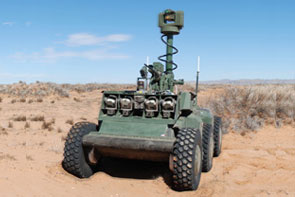
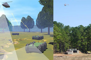
The PerceptOR program’s goal was to improve the ability of unmanned ground vehicles (UGVs) to navigate autonomously. NREC was the only organization that participated in all three phases of the program.
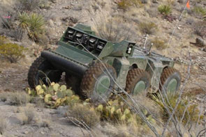
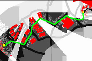
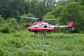
The NREC team developed an autonomous UGV that was guided by a small unmanned helicopter (flying eye). The flying eye scouted the terrain ahead of the UGV to detect hazards at long range. The UGV’s extensive onboard sensor suite detected close-range and mid-range hazards and confirmed the existence of obstacles seen from the air. Combining these two sources of terrain data allowed the UGV to plan paths that avoided dangerous areas.
The PerceptOR program’s technology has been transitioned to the UPI, LAGR and ANS programs.APPLICATION
The Problem
Today’s unmanned ground vehicles (UGVs) require constant human oversight and extensive communications resources particularly when traversing complex, cross country terrains. UGVs cannot support tactical military operations in a large scale way until they are able to navigate safely on their own and without constant human supervision. Off all classes of obstacles, UGVs are particularly vulnerable to "negative obstacles" like a hole or a ditch, which are difficult for a ground vehicle to sense due to the limited range and height of on-board sensors.
The Solution
The NREC-led team developed an innovative PerceptOR "Blitz” concept — an integrated air/ground vehicle system that incorporates significant autonomous perception, reasoning and planning for unmanned ground vehicles.
The autonomous UGV included LADAR, three stereo camera pairs, intra- and inter-vehicle sensor fusion, terrain classification, obstacle avoidance, waypoint navigation and dynamic path planning. The unmanned air vehicle — the Flying Eye — views the terrain from above, an optimal vantage point for detecting obstacles such as ruts, ditches and cul de sacs.
The team successfully demonstrated the UGV and Flying Eye working collaboratively to improve navigation performance. The UGV planned its initial route based on all available data and transmitted the route to the Flying Eye. The Flying Eye flew toward a point on this route ahead of the UGV. As the Flying Eye maneuvered, its downward looking sensor detects obstacles on the ground. The location of these obstacles was transmitted back to the UGV in relation to the UGV’s position. The UGV replans its intended path to avoid the obstacles and directs the Flying Eye to scout the new path.
The improved obstacle sensing capabilities (due to dual, well-separated views) and the optimized route planning (enabled by the Flying Eye's reconnaissance) increase the UGV’s autonomous speed by decreasing the risk of the vehicle being disabled or trapped, and by reducing the need for operator intervention and communications system bandwidth.DESCRIPTION
Working in collaboration with its subcontractors, NREC developed the PerceptOR Blitz solution in a three-phase program.
In Phase I, the team developed a vehicle perception system prototype that included three sensing modalities, sensor fusion, terrain classification software, waypoint navigation and path planning software. A commercial ATV, retrofitted for computer control, served as the perception system platform.
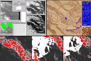
In Phase II, the team validated the PerceptOR prototype on unrehearsed courses at test sites spanning four distinctly different types of terrain: sparse woods in Virginia; desert scrub with washes, gullies and ledges in Arizona; mountain slopes with pine forests in California; and dense woods with tall grass and other vegetation in Louisiana. During the test runs, the team demonstrated fully integrated unmanned, air/ground sensing that was used to detect and avoid negative obstacles and other hazards. They also negotiated complex terrain using only passive sensing. Additionally, they classified difficult terrain types (ground cover, meter-high vegetation, desert scrub) by fusing geometric and color sensor data.
In Phase III, the NREC team continues to improve the performance and reliability of the perception system with additional development and field trials. The team advanced UGV autonomous capabilities for operating in sub-optimal conditions, such as with obscurants (dust, smoke or rain), degraded GPS coverage, and reduced communications bandwidth.
Automated Mowing
- OVERVIEW
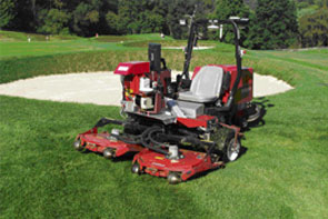
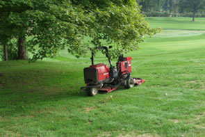
NREC collaborated with the Toro Company to develop a prototype autonomous mower that can be used in the maintenance of a golf course, sports field or commercial landscape.
NREC scientists and engineers developed a robotic mower that can mow a golf course autonomously, safely and precisely, while sensing and avoiding small obstacles (like golf balls) reliably.
Automated mowing reduces the need for human operators, allowing them to concentrate on other tasks for optimization of labor costs. The system also reduces the need to operate mowers during peak golfing hours, resulting in a more pleasant golfing experience.APPLICATION
The Problem
Golf courses require constant maintenance and routinely bear high labor costs for teams of semi-skilled operators to mow fairways, frequently at peak golfing times. Mower operators must avoid golfers, maintain a neat appearance, combat fatigue and operate the mower safely.
The Solution
NREC’s autonomous mower system meets these demands by providing a system that requires a minimal amount of supervision that can be operated at night and during other off-peak hours.
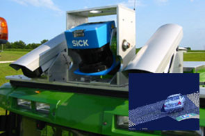
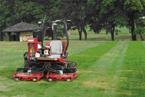
The autonomous mower has a highly reliable obstacle detection and localization system. NREC developed an obstacle detection system that includes a sweeping laser rangefinder, which builds a 3D map of the area in front of the mower. It "learns” and uses this map to detect obstacles along the way. The robotic mower’s localization system combines GPS and inertial data to provide a position estimate that is accurate and robust.DESCRIPTION
To achieve complete automation on golf courses and sports fields, NREC scientists and engineers developed capabilities for reliable obstacle detection, precise navigation and effective coverage.
Reliable obstacle detection:- NREC designed the system so that it recognizes true obstacles, as small as a golf ball, while not generating false positives, to keep the vehicle safe.
- NREC engineers continue to refine the system so that it will discriminate true obstacles from tall grass.
Precise navigation:
- NREC’s autonomous mower operates with centimeter-level precision to create the cross-hatch patterns seen on premier golf courses.
- NREC robotics engineers continue to refine the system to improve its reliability in areas of minimal GPS coverage.
Effective coverage:
- NREC designed the robotic mower to follow patterns that enable it cover the entire fairway efficiently.
- NREC's software engineers continue to refine the system's interface for enhanced ease-of-use.
Automated Harvesting
- OVERVIEW
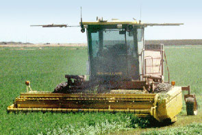
NREC produced a new class of robotic harvesters that increase efficiency and productivity in agriculture by reducing reliance on human operators.
The automated harvesting project targeted three levels of automation:- A "cruise control” feature to automatically steer, drive and control the harvesting header, thereby allowing allow the operator to focus on other in-cab controls and harvest conditions.
- A GPS-based "teach/playback” system to enable the harvester to "learn” a field and then repeat a given path, thereby allowing one operator to remotely control several harvesters.
- A fully autonomous harvester using vision perception to completely harvest a field with no human supervision.
APPLICATION
The Problem
Farmers struggle constantly to keep costs down and productivity up. Mechanical harvesters and many other agricultural machines require expert drivers to work effectively. Labor costs and operator fatigue, however, increase expenses and limit the productivity of these machines.
The Solution
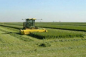
In partnership with project sponsors NASA and New Holland, Inc., NREC built the a robotic harvester, which harvests crops to an accuracy of 10cm by using a combination of a software-based teach/playback system and GPS-based satellite positioning techniques. Capable of operating day and night, the robot can harvest crops consistently at speeds and quality exceeding what a human operator can maintain.
Tangible results from extensive field tests conducted in El Centro, California demonstrated that an automated harvester would increase efficiency; reduce cost and produce better crop yield with less effort.DESCRIPTION
For robot positioning and navigation, NREC implemented a differential GPS-based teach/playback system. Differential GPS involves the cooperation of two receivers, one that's stationary and another that's roving around making position measurements. The stationary receiver is the key. It ties all the satellite measurements into a solid local reference.
With the teach/playback system, the Windrower "learns" the field it is cutting, store the path in memory and then is programmed to repeat the path on its own.
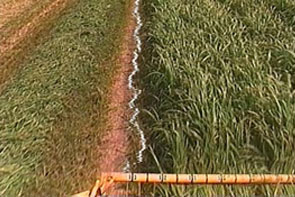
Early in the project, the NREC team used color segmentation to determine the cut line for machine servoing. The approach differentiates the percentage of green representing the standing crop and the brown stubble of the cut crop. The system’s computer scans the cut line to determine machine direction. The Windrower is guided at speeds of 4–8 mph to about a 3-inch variance from this crop line.
Other guidance and safety instruments include an inclinometer to protect the machine from rollover and tipover and a gyroscope for redundant guidance.
Autonomous Peat Moss Harvesting
- OVERVIEW
NREC developed an add-on perception system for automating peat moss harvesting.
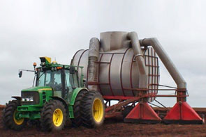
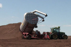
NREC integrated its add-on perception packages onto a team of three computer-controlled tractors developed by John Deere. These autonomous tractors were used in harvesting operations in a peat bog.
The robotic peat harvesting team was continuously tested for a full season, completing over 100 harvesting missions in a working peat bog. Their behavior imitated manual peat harvesting operations while maintaining a safe operating environment.APPLICATION
Peat moss is commonly used in gardening and plant growing. It is accumulated, partially decayed plant material that is found in bogs. An active peat bog is divided into smaller, rectangular fields that are surrounded by drainage ditches on three sides. When the top layer of peat is dry, the fields are ready to be harvested. Harvesting is done daily, weather permitting.
Peat is harvested with tractor-pulled vacuum harvesters. The vacuum harvesters suck up the top layer of dry peat as they’re pulled across a peat field. When the harvester is full, its operator dumps the harvested peat onto storage piles. The stored peat is later hauled away to be processed and packaged.
Peat moss harvesting is a good candidate for automation for several reasons:- Peat fields have a well-defined, structured environment.
- Peat bogs are largely free of obstacles and vegetation.
- The manual harvesting process lends itself well to automation.
- Peat bogs are located in remote areas, where there are often shortages of qualified operators. This provides an incentive to automate the harvesting process.
DESCRIPTION
NREC’s add-on perception system performs three tasks that are important for safe autonomous operation.
Detecting Peat Storage Piles
Before it can dump the harvested peat onto a storage pile, the robot needs to find the edge of the pile. However, it cannot rely on GPS because the storage piles change shape, size and location as harvested peat is added to them. To locate the edges of storage piles, the perception system finds contiguous areas of high slope in the sensed 3D ground surface. A probabilistic spatial model of the ground surface generates smoothed estimates of ground height and handles sensor noise.Detecting Obstacles
Although peat fields are generally free of obstacles, the harvesters must detect the presence of obstacles such as people, other harvesters, and other vehicles) to ensure safe unmanned operation. To detect different types of objects, the perception system uses a combination of algorithms that make use of 3D ladar data to find dense regions, tall objects, and hot regions above the ground surface.
Detecting Ditches
Ditch locations are mapped with GPS. However, as an added safety precaution, they are also detected by the perception system. The perception system searches for ditch shapes in the smoothed estimate of ground height.
RVCA
- OVERVIEW
NREC is implementing an end-to-end control architecture for unmanned ground vehicles (UGVs) to reduce integration risk in the US Army’s Future Combat Systems (FCS) program.
The Robotic Vehicle Control Architecture (RVCA) program demonstrates whether autonomous UGV operations can be successfully carried out with FCS representative system-of-system hardware and software components. Its rigorous, ongoing field testing unites the powerful Crusher UGV with the advanced capabilities of the Autonomous Navigation System (ANS) and other FCS components.APPLICATION
RVCA provides the following benefits to FCS:- Verifies how ANS functions on a UGV platform
- Assesses UGV control with representative FCS hardware and software components operating within FCS network constraints
- Provides feedback that influences the development of FCS Battle Command software
- Reduces force integration risk for FCS
- Expedites the delivery of unmanned systems to soldiers in the field
DESCRIPTION
RVCA consists of the following:- A UGV platform with integrated ANS hardware and software. Currently, RVCA is using the rugged, highly-mobile Crusher UGV platform. Later in the program, RVCA technology will be integrated onto the APD platform.
- Integrated System of System Common Operating Environment (SOSCOE) in both manned and unmanned vehicle platforms Integrated Vehicle Management System (VMS) and Integrated Computer System (ICS) to control a UGV
- Supporting data for operation of a UGV using these components in a networked environment
Engineering evaluations in the field focus on capabilities such as waypoint following, teleoperation, the system’s overall performance with ANS and other software components, and its use by soldiers in the field. The program concludes in 2010 with a Soldier Operational Experiment.
Innovative Mechanisms
Pipeline Explorer
- OVERVIEW
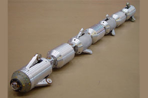
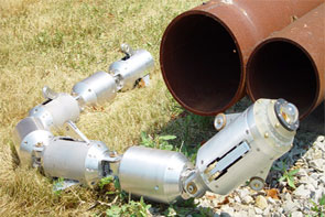
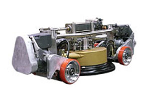
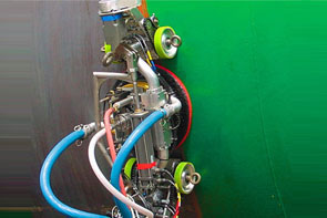
NREC designed, built and deployed Pipeline Explorer, the first untethered, remotely-controlled robot for inspecting live underground natural gas distribution pipelines.
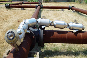
Explorer represents the state of the art in remote-controlled inspection systems for low-pressure and high-pressure natural gas pipelines. The battery-powered Explorer can perform long-range, extended duration visual inspections of cast-iron and steel gas mains. Unlike older, tethered systems, Explorer can inspect thousands of feet of pipeline from a single excavation point. An operator controls Explorer through a wireless link and can monitor pipeline images in real time.
Explorer won an R&D Magazine Top 100 award in 2006 for being one of the year’s most original and innovative technological developments.APPLICATION
The Problem
With an aging gas pipeline infrastructure, utilities face ever-increasing needs for more frequent inspections of the distribution network. Conventional pipe-inspection methods require frequent access excavations for the use of push-pull tethered systems with an inspection range of no more than 100 to 200 feet per excavation. This results in multiple, costly and lengthy inspections for multi-mile sections of pipe in search of data needed for decisions on pipeline rehabilitation.
The Solution
The Explorer system can access thousands of feet of pipeline from a single excavation. It collects real-time visual inspection data and provides immediate remote feedback to the operator for decisions relating to water intrusion or other defects. This information is collected faster and at a lower cost than can be obtained via conventional methods.
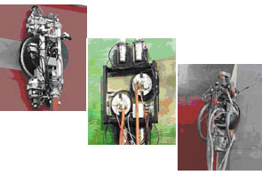
The robot’s architecture is symmetric. A seven-element articulated body design houses a mirror-image arrangement of locomotor/camera modules, battery carrying modules, and locomotor support modules, with a computing and electronics module in the middle. The robot’s computer and electronics are protected in purged and pressurized housings. Articulated joints connect each module to the next. The locomotor modules are connected to their neighbors with pitch-roll joints, while the others are connected via pitch-only joints. These specially designed joints allow orientation of the robot within the pipe, in any direction needed.
The locomotor module houses a mini fish-eye camera, along with its lens and lighting elements. The camera has a 190-degree field of view and provides high-resolution color images of the pipe’s interior. The locomotor module also houses dual drive actuators designed to allow for the deployment and retraction of three legs equipped with custom-molded driving wheels. The robot can sustain speeds of up to four inches per second. However, inspection speeds are typically lower than that in order for the operator to obtain an image that can be processed.
Given that each locomotor has its own camera, the system provides views at either end to allow observation during travel in both directions. The image management system allows for the operator to observe either of the two views or both of them simultaneously on his or her screen.DESCRIPTION
In developing Explorer, NREC performed requirements analysis, system simulation, design and engineering, prototype fabrication and field testing. NREC worked closely with natural gas distribution utilities across the country to arrive at a versatile and suitable design. The robot was extensively tested over the 2.5 year development period. This testing included week-long runs of multiple 8-hour days in live explosive environments for cast-iron and steel pipelines across the northeastern U.S.
The system is currently undergoing an upgrading phase, in which NDE sensors are being added and the system improved based on field trial results. Continued development of these new inspection methods will aid in maintaining the high integrity and operation reliability of the nation’s natural gas pipeline infrastructure.
Container Handling System
- OVERVIEW
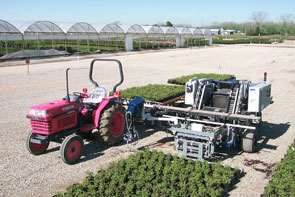
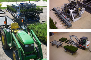
NREC developed autonomous and semi-autonomous robotic systems for moving containerized plants to and from the field.
NREC’s robotic field-container handling systems make the labor-intensive process of moving containerized plants more efficient. Both the autonomous and semi-autonomous systems handled the task of picking up, moving, and setting down multiple containers at the same time. This reduces the horticulture industry's reliance on manual labor, increases nursery productivity, improves field safety, and reduces plant handling costs.APPLICATION
The Problem
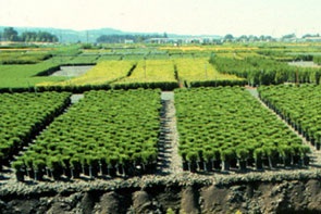
U.S. ornamental horticulture is an $11 billion dollar a year industry tied to a dwindling migrant work force. Unskilled seasonal labor is becoming more costly and harder to find, but it is still needed several times a year to move potted plants to and from fields and sheds. The nursery industry must address this problem if it is to survive and continue to flourish. The challenge has been to develop an adaptable container-handling solution that is cost-effective, easy to operate and maintain with minimal technical skills and easily adaptable to a variety of containers and field conditions.
The Solution
Working in collaboration with NASA and project sponsor the Horticultural Research Institute (HRI), NREC developed solutions that efficiently handle a variety different container sizes with a broad range of plant materials.
The automated container handling systems were designed to efficiently manage the following processes: moving containers from the potting machine/shed to the field; coordinating in-field container spacing; and moving containers into and out of-over-wintering houses.
The prototype and field tested systems were designed to handle 35,000 containers per 8-hour day with one or two operators. The resulting benefits include:- Direct labor cost savings due to the reduced number of seasonal workers required for the simple task of moving potted plants
- Reduced risk of injuries in the field
- Speedier, more efficient processes for moving and handling large numbers of plant containers In the field, the system can be re-configured easily to best suit changing conditions, container sizes and end-user needs.
In the field, the system can be re-configured easily to best suit changing conditions, container sizes and end-user needs.
DESCRIPTION
The Junior (JR) container handling system represents a self-mobile outdoor platform powered by an internal combustion engine, perceiving containers through a laser range-finder, controlled through an on-board PLC computer, and actuated through a set of electro-hydraulic and electro-mechanical actuation systems.
Performance and operational data was obtained during field trials of JR and presented to the sponsor. JR had adequate performance but was not at a price point that enabled it to be readily accepted in the industry.
Project sponsor HRI then asked the NREC to adapt JR technology to a lower cost attachment. This attachment must interface to an existing prime mover and handle larger sized containers.
The NREC team took the critical technologies developed and tested in JR and applied them directly to an attachment for a mini-excavator (PotCLAW). The technologies include laser-based pot position sensing and interpretation and the mechanism designs required for reliable and robust "grabbing” of the pots. PotCLAW performs the same function as JR except that an operator handles all coarse positioning of the grabber head for both loading and unloading operations. All fine positioning and pot position sensing is performed automatically exactly as in the JR system.
PotClaw was demonstrated to the Sponsor at NREC facilities and delivered to a local nursery for field testing and demonstration to end users.
The system is a commercially viable product that is available for licensing.
EnvirobotTM - Paint Removal
- OVERVIEW
NREC designed, built and tested the centerpiece of a semi-automated paint removal system that is now in everyday use and available for commercial sale by Chariot Robotics, LLC
The EnvirobotTM is the world's most technologically advanced system for removing paint and coatings from steel surfaces. Controlled via wireless joystick, it uses patented air gap magnets to glide effortlessly across the sides and bottoms of ship hulls, storage tanks and other steel structures, reaching speeds of up to 51 cm/sec (20 in/sec). Spinning high-pressure water jets remove paint without marring the underlying surface while a powerful vacuum and patented, EPA-approved filtration system recover wastewater and debris.
The EnvirobotTM system reduces pollution, lowers paint stripping and sweeping costs, and shortens dry dock stays. It has received widespread recognition for technical innovation (read the Fortune 500 article) and protecting the environment.APPLICATION
The Problem
The conventional method of grit blasting creates toxic airborne dust during the blasting as well as 40 lb. of toxic waste per square foot cleaned. This endangers shipyard workers and creates an expensive disposal problem. The grit-based method also drives grit into the hull surface where it decreases the adhesive properties of the paint. While single-stream high-pressure water guns are also used, they remove paint very slowly and do nothing to contain toxic marine paint run-off.
The Solution
The EnvirobotTM robotic system uses ultra-high-pressure water jets (55,000 psi) to strip the hull down to bare metal. Multiple nozzles in a spinning head remove coatings in a wide swath, not inch by inch. It can remove coatings at a rate of 500 to 3000 square feet per hour, depending on how many layers of the coating are being removed.
Magnets hold it securely and enable it to roll almost anywhere. All the water used in the stripping is recovered by a powerful vacuum system and recycled. The only residue of the cleaning is the paint itself, which is automatically dumped into containers for proper disposal.
Moreover, the water-based stripping process produces a much cleaner metal surface, which greatly increases the life of the paint applied to the ship. Compared to any form of sand- or grit-blasting, a hydroblasted surface is easily proven to rust less, and to allow paint to adhere better.DESCRIPTION
In developing the EnvirobotTM, NREC performed requirements analysis, system simulation, design and engineering, prototype fabrication and field testing. Facing incomplete and dynamic requirements, NREC developed three version of the robot with each successive version delivering more performance, flexibility, and reliability.
The robots were extensively tested over the two-year development period. This testing included week-long runs of 24 hours per day using inexperienced operators under real-world conditions. The NREC team conducted the testing on a specially designed test wall made up of flat, concave, convex and underside surfaces and connecting weld beads. Following these tests, the team participated in field trials at several shipyards and, based on that experience, implemented a dozen engineering programs to improve reliability and supportability of the robot.
Robotic All-Terrain Surveyor (RATS)
- OVERVIEW
NREC is researching and developing all-terrain hopping robots for space, search and rescue, and defense applications.
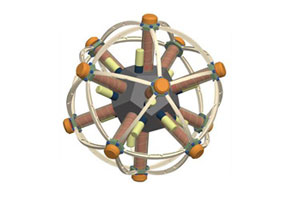
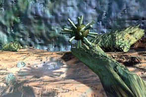
The symmetric, multi-legged Robotic All-Terrain Surveyor (RATS) combines hopping and rolling to move around in rugged environments.
Potential RATS missions include deploying sensors, operating as mobile communications relays, carrying out search and rescue operations, and performing long-range planetary survey missions in low gravity environments.APPLICATION
RATS moves by actuating its legs in sequence. By firing one or more legs in a controlled pattern, it can roll along the ground and jump over rocks, holes and other obstructions. This hopping ability allows it to overcome obstacles that would be difficult or impossible for a similarly-sized robot with wheels or treads to handle.
RATS’ symmetric design and spherical shape allow it to travel in any direction and tumble and bounce freely. Precise coordination of its multiple legs gives it very fine movement control and maneuverability in tight spaces.DESCRIPTION
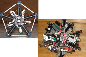
NREC researchers have built two RATS prototypes.
Planar prototype
The planar prototype is a simplified version of the spherical RATS. Its five symmetric legs are actuated pneumatically with compressed air from a solenoid valve. The robot is tethered on a boom through its center and travels in a circle.
The planar prototype was used to study control strategies and gaits for RATS. By controlling the firing sequence of its legs, researchers were able to develop a sustainable running gait and a hopping gait for surmounting obstacles. It uses a feedback controller to maintain maximum speed.
Spherical prototype
The spherical prototype is a preliminary version of the full, spherical RATS. Its twelve symmetric legs are activated by servos.
The spherical prototype can travel freely across the ground and was used to develop walking gaits for RATS. It uses a discrete sequencing controller in open loop mode to follow a path.
Unmanned Vehicle Design
Dragon Runner
- OVERVIEW
NREC collaborated with Automatika, Inc. (AI) to develop Dragon Runner, an ultra-rugged, portable, lightweight reconnaissance robot for use by the U.S. Marine Corps in Operation Iraqi Freedom (OIF) for urban reconnaissance and sentry missions.
Dragon Runner represents the state-of-the-art in rugged ultra-compact, ultra-portable mission-capable mobile robotics platform for use with wireless remote control.
The use of small-scale hand controllers and custom mission backpack, powered through military batteries, make this system ideal for use in areas too dangerous or inaccessible for Marines.APPLICATION
The Problem
Reconnaissance and sentry missions in urban environments are risky military operations. Small groups of warfighters use stealth and rapid maneuvering to locate and gather information on the enemy. A remote-controlled robot system, capable of scouting ahead and out of small arms range, would provide extended and safer reconnaissance capability without exposing warfighters to potentially lethal situations.
The Solution
Dragon Runner provides a small-profile, stealthy, lightweight solution to allow warfighters to rapidly gather intelligence and perform sentry-monitoring operations.
The four-wheeled device is small and light enough to be carried in a soldier's backpack and rugged enough to be tossed over fences and up or down stairwells. Its low weight and compact size produce little to no impact on the warfighter’s pace, fighting ability and load-carrying needs (food, water, ammo). These attributes are the key differentiators to other robot systems which are heavier, bulkier, slower, and take longer to deploy.DESCRIPTION
Objectives:
Dragon Runner was developed as a low-cost rugged alternative to overly heavy, bulky, slow and costly robotic scouts already on the market. Dragon Runner pushed the technical state-of-the-art in the areas of drivetrain, vetronics, miniaturization and integration, as well as portability-integration (backpack), small desert-usable displays, and interface and production-ready injection-moldable materials and parts for low-cost assembly. NREC met all objectives, including the development and testing of several modular payloads.
System Description:
The prototype Dragon Runner mobile ground sensor system consists of a vehicle, a small operator control system (OCS), and a simple ambidextrous handheld controller for one-handed operation, all held in a custom backpack.
The four-wheeled, all-wheel-drive robotic vehicle has high-speed capability and can also be operated with slow, deliberate, finite control. The system is easy to operate, requires little formal operator training and can be deployed from the pack in less than three seconds. On-board infrared capabilities enable night operation.
NREC delivered several units for deployment to OIF for the Marines to evaluate effectiveness and develop techniques, tactics and procedures.
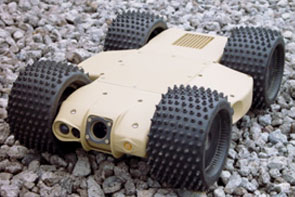
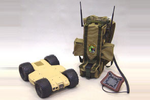

Unmanned Ground Combat Vehicle - UGCV
- OVERVIEW
With development of the Spinner unmanned ground vehicle, an NREC-led team delivered technical breakthroughs in mobility, mission endurance and payload fraction.
DARPA created the Unmanned Ground Combat Vehicle (UGCV) program to develop vehicle prototypes based on novel designs unrestrained by the need to accommodate human crews. The resulting prototypes demonstrate advanced configurations and technology that are applicable to UGV design programs for the US Army’s Future Combat System (FCS).
NREC with its three first level subcontractors (Boeing, Timoney Technology and DRS-TEM) developed and tested Spinner, a highly durable, invertible, six-wheel-drive, hybrid-powered vehicle that responds to the need of a UGCV to surmount challenging terrain obstacles, be easily teleoperated, and able to withstand an occasional moderate crash and rapidly recover.
Spinner’s impressive field results in the final phase of UGCV convinced DARPA to award a large follow-on program named UPI that integrates PerceptOR autonomy with the Spinner platform.APPLICATION
The next generation of autonomous military vehicles must have an extraordinary capability to surmount terrain obstacles, as well as survive and recover from impacts with obstacles and unpredictable terrain. They must also be fuel efficient and highly reliable so that they can conduct long missions with minimal logistical support.
Resilience, or a vehicle’s ability to withstand considerable abuse during a mission and continue, achieving forward progress, became a key driver as the UGCV program evolved. Such abuse is common to unmanned vehicles that are controlled by distant teleoperators or by semi-autonomous sensors and software.
To focus prototype development, DARPA established primary design metrics:- Obstacle capability (1m+ positive, 2m negative, 35 slopes)
- Resilience (withstand abusive use while remaining lightweight)
- Endurance (14-day missions; 450 km range without refueling)
- Payload Fraction (>25% of gross vehicle weight)
Spinner’s demonstrated performance during two years of intense testing in extremely rugged terrain exceeded these metrics.
Spinner takes maximal advantage of the uncrewed UGCV aspect through its inverting design as well as the unique hull configuration that accommodates its large continuous payload bay, which rotates to position payloads upright or downward. In addition to rollover crash survivability, the hull, suspension and wheels have been designed for extreme frontal impacts from striking a tree, rock or unseen ditch at speed. Despite its large size, Spinner is very stealthy due to its low profile and quiet hybrid operation.DESCRIPTION
As prime contractor, NREC managed the performance of over 30 trade studies, risk reduction activities, subsystem design and test activities. NREC also led all integration and assembly operations, and executed all performance testing. Additionally, NREC was responsible for many subsystems, including thermal management, prime power, ride height control, braking, safety, command station, OCU, communications, and teleoperation. Moreover, NREC developed all the vehicle positioning, automation, data gathering and data analysis systems that were used on a continuous basis to test the vehicle.
Following design, fabrication and assembly, Spinner completed two years of intense testing to assess its capability in a variety of terrains, weather conditions, and operational scenarios. For example, during a government-controlled field test at the Yuma, Arizona Proving Grounds, Spinner covered nearly 100 miles of very rough off-road terrain.
Overall, Spinner has traveled hundreds of miles on varied off-road terrains while under automated guidance, as well as under direct human control. Results continue to indicate that many of the technologies and approaches used in Spinner are viable options for UGVs in the future.
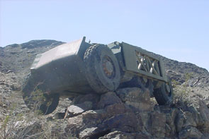
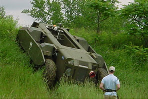
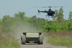
Tactical Unmanned Ground Vehicle - TUGV
- OVERVIEW
NREC designed, developed, field tested and successfully demonstrated a high-mobility tactical unmanned ground vehicle (TUGV) for the United States Marine Corps.
The rugged, highly mobile TUGV was designed to support expeditionary units operating ahead of the main force. It includes a six-wheeled base unit, interchangeable mission payload modules, and a wireless data link. TUGV is operated with a hand-held controller and helmet-mounted view screen; the entire operator control unit (OCU) fits in a backpack.APPLICATION
TUGV gives infantry a way to remotely perform combat tasks, which reduces risk and neutralizes threats. It is designed to support dismounted infantry in missions that span the range of military operations. Missions that TUGV can perform include:- Day and night reconnaissance
- Remote surveillance and target acquisition (RSTA)
- Detecting nuclear, biological and chemical (NBC) agents
- Obstacle breaching
- Direct fire
TUGV’s operator and supported unit can remain concealed when it goes into action, improving their safety.
DESCRIPTION
TUGV is capable of fast off-road driving in extreme terrain and can withstand harsh environments and high altitudes. Its all-wheel drive with run-flat tires ensures mobility under hazardous conditions. TUGV’s quiet hybrid-electric drive supports missions up to 24 hours long (4 hours on battery power alone).
Versatile payload modules, open hardware, and JAUS-compliant, modular software allow quick mission reconfiguration. TUGV has universal tactical mounts for M249 and M240G machine guns, Soldier-launched Multi-purpose Assault Weapon (SMAW), Light Vehicle Obscuration Smoke System (LVOSS) and Anti-Personnel Obstacle Breaching System (APOBS).
TUGV’s operator control unit (OCU) has a rugged, helmet-mounted display with a game controller-style hand controller and lightweight CPU, all of which fit into a backpack. The OCU also has a built-in omni-directional antenna, throat microphone and earpiece. A remote data terminal can act as a spare OCU.
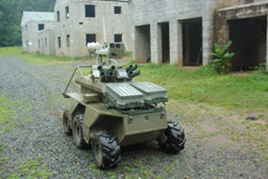
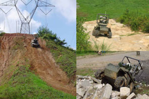
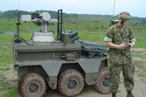
Crusher
- OVERVIEW
View CMU press release.
View DARPA press release.View News Links
NREC designed and developed the Crusher vehicle to support the UPI program's rigorous field experimentation schedule.
The UPI program features quarterly field experiments that assess the capabilities of large scale, unmanned ground vehicles (UGV) operating autonomously in a wide range of complex, off-road terrains. UPI's aggressive mobility, autonomy and mission performance objectives required two additional test platforms that could accommodate a variety of mission payloads and state of the art autonomy technology.
Crusher represents the next generation of the original Spinner platform, the world's first greater-than-6-ton, cross-country UGV designed from the ground up. Crusher offers more mobility, reliability, maintainability and flexibility than Spinner, at 29 percent less weight.APPLICATION
As a core building block in the Army's future force, tactical UGVs enable new war-fighting capabilities while putting fewer soldiers in harm's way. The full benefit of this new capability can only be achieved with field-validated understanding of UGV technology limits and consideration of the impact to Army doctrine, personnel, platforms and infrastructure.
UPI experiments encompass vehicle safety, the effects of limited communications bandwidth and GPS infrastructure on vehicle performance, and how vehicles and their payloads can be effectively operated and supervised.
By mid 2006, NREC will integrate its latest automation technology onto both Crusher vehicles. A combination of ladar and camera systems allow the vehicles to dynamically react to obstacles and travel through mission waypoints spaced over a kilometer apart. The use of overhead data via terrain data analysis will continue to be utilized for global planning. Over the next year these two vehicles will analyze, plan, and execute mobility missions over extreme terrains without any human interaction at all. Crusher’s suspension system allows it to maintain high offroad speeds across extreme terrains.DESCRIPTION
Crusher has a new space frame hull designed by CTC Technologies and made from high-strength aluminum tubes and titanium nodes. A suspended and shock-mounted skid plate made from high-strength steel allows Crusher to shrug off massive, below-hull strikes from boulders and tree stumps. The nose was completely redesigned for Crusher to sustain normal impacts with trees and brush while also absorbing the impact of major collisions.
Suspensions designed by Timoney support 30 in. of travel with selectable stiffness and reconfigurable ride height. Crusher can comfortably carry over 8000 lbs. of payload and armor. Crusher's hybrid electric system allows the vehicle to move silently on one battery charge over miles of extreme terrain. A 60kW turbo diesel engine maintains charge on the high-performance SAFT-built lithium ion battery module. Engine and batteries work intelligently to deliver power to Crusher's 6-wheel motor-in-hub drive system built around UQM traction motors.
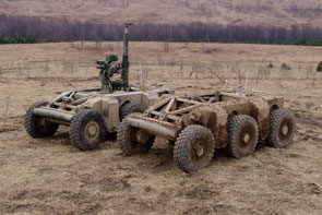
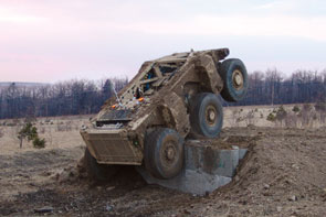
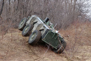
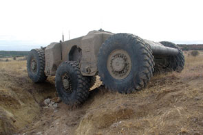
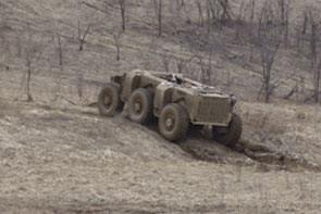
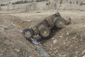
Autonomous Platform Demonstrator (APD)
- OVERVIEW
The Autonomous Platform Demonstrator (APD) will develop, integrate and test next-generation unmanned ground vehicle (UGV) technologies.
These technologies include hybrid-electric drive systems, advanced vehicle suspension systems, and lightweight chassis technologies on a single platform. APD’s development is based upon Future Combat Systems (FCS) requirements and specifications, including weight, mobility, performance and size. It will ultimately serve as a large-scale UGV integration platform for demonstrating technologies developed under the Robotic Vehicle Control Architecture (RVCA) project.APPLICATION
The APD project will continue the development and maturation of UGV core mobility technologies. This effort will benefit all unmanned platform mobility, subsystem and control development.
APD will ultimately be used as a highly-mobile UGV platform demonstrator for the RVCA program, replacing the Crusher UGV.
APD’s key performance parameters include a top speed of 80 kilometers per hour and the ability to autonomously perform a single lane change. Its size requirements include the ability to deploy two vehicles on a C-130 transport plane.DESCRIPTION
The 80 kph speed requirement presents the most significant challenge for NREC designers to meet for a skid-steered vehicle. To address this requirement and others the NREC team completed in-depth trade studies in suspension technology and configuration, hull structure, vehicle drive architectures, battery technology, cooling approach and engines.
The team successfully completed Preliminary Design Review in August 2008. They target vehicle rollout in August 2009. Following rollout, APD will undergo extensive mobility testing and ultimately replace Crusher as the primary RVCA test platform. The program culminates in Soldier Operation Experiments in 2010.
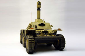
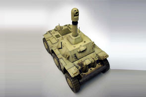
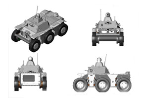
Sensing & Image Processing Applications
Caisson Construction 3D Modeling
- OVERVIEW
NREC developed a 3D imaging system for underwater excavation and placement of caissons that Kajima Corporation used to support the foundation for the Nagasaki Bay Bridge.
Kajima contracted with NREC to develop an imaging sensor system that could see through dust and effectively map and display the interior of the caisson digging area to personnel operating below ground cutters. In less than one year, NREC designed, built and fielded the system in Japan where it supported the placement of a 42 meter deep caisson in solid bed rock.
The 3D sensor system reduced labor cost by enabling more efficient tele-operation of the caisson cutting and material removal process. It increased safety by reducing the need for workers to directly inspect the pressurized excavation site.APPLICATION
The Problem
In the early stages of constructing the Nagasaki Bay Bridge, Kajima was faced with the challenge of sinking caissons underwater and conducting underwater excavation through solid bedrock. Deploying workers in these conditions is extremely hazardous and costly. Above ground personnel tele-operating three large cutting arms rely on images from cameras installed below. The cameras could not see through dust nor provide enough depth perception for effective remote excavation.
The Solution
NREC scientists developed a 3D sensor based upon structured light technology and a display system that Kajima used successfully to provide 3D maps of the excavated area. The mobile system provided new images every 5 minutes and focused on the critical perimeter area, while effectively seeing through dust.DESCRIPTION
INREC's 3D imaging system surveys the entire caisson work area and focusses on the perimeter of the excavation area, where the cutter may damage the caisson or become entrapped between the rock and the caisson edge. The system utilizes:- Structured light sensors, consisting of a fan laser and three cameras, with integrated control and data processing, mounted on a battery-powered mobile carriage, which rides on a track mounted inside the caisson wall
- A wireless Ethernet data link that transmits the sensory data to a stationary charging station, which is located inside the caisson and relays the data to an above-ground operations center
- An image processor that integrates the data from the imaging sensors, cutting arm joint position sensors, and the user commands to generate a three-dimensional model of the excavation area for operator monitoring.
The interactive display, which functions as a virtual camera for the operator, shows the position of the cutting arms and the distribution of material to be removed. The sensor data is processed and displayed at three separate operator stations. Each operator can manipulate and view the data independently to suit his or her viewing needs.
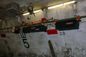
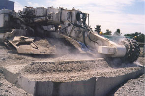
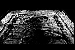
Medical Image Registration
- OVERVIEW
NREC designed and implemented a medical image registration system to accurately estimate a patient’s position for therapy.
For radiotherapy and other forms of therapy to be successful, patients must be correctly positioned for treatment. The medical image registration system uses two-dimensional X-rays and three-dimensional CT scans to accurately estimate the position and orientation of a patient’s anatomy with respect to an external coordinate frame.
High-speed computer graphics algorithms render simulated X-rays from CT scan data in a fraction of a second. These high-resolution, simulated radiographs are compared with actual X-ray images using a novel image comparison algorithm. The comparison algorithm ignores noise in the images and clutter from the patient's other anatomy to correctly estimate the patient's position.
The system achieved sub-millimeter registration accuracies in preliminary tests, with total registration times on the order of 50 seconds. Tests using clinical patient data are underway.APPLICATION
The Problem
Patient registration for computer assisted surgery is a challenging problem requiring short registration times and high accuracies. Registration algorithms typically involve trade-offs between speed of execution, accuracy, and ease of application. Image-based registration algorithms, which gather data from large portions of the image in order to increase accuracy, are computationally intensive, and typically suffer performance degradation when the input images contain clutter.
The Solution
CMU has developed an image-comparison algorithm, Variance-Weighted Sum of Local Normalized Correlation, which greatly decreases the impact of clutter and unrelated objects in the input radiographs. This image comparison approach is combined with hardware-accelerated rendering of simulated X-ray images to permit registration of noisy, cluttered images with sub-millimeter accuracy.DESCRIPTION
This project began as an effort to commercialize technology from on-campus research. NREC worked with the sponsor to define project requirements, and to ensure that activities at CMU complied with the sponsor's rigorous process for product design, review, and testing.
In order to minimize the risk of vendor lock-in, the resulting product was built to run under the Open Source LINUX operating system, and uses only off-the-shelf commodity hardware.
The project deliverables, including over 2000 pages of design, traceability, test, reference, and risk analysis documentation, have been transferred to the sponsor. The software is currently undergoing additional testing and product integration at the sponsor site.
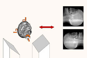
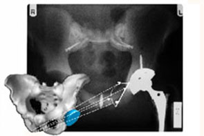
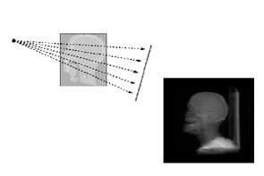
Conveyor Belt Inspection System
- OVERVIEW
NREC designed, built and tested a high-speed "machine vision" system for monitoring the condition of conveyor belts such as those used in underground coal mines. This system is in everyday use at mines operated by CONSOL Energy, Inc., and it is available for purchase from Beitzel Corp., which licensed the technology from CONSOL and Carnegie Mellon.
NREC developed the patented machine vision system as part of an innovative belt inspection system designed to reduce costly downtime caused by degradation of conveyor belt splices.
Developed in collaboration with project partners CONSOL Energy, Inc. and Beitzel Corporation, the system incorporates a computer workstation that monitors and records digital images obtained from cameras mounted above the conveyor belt to provide continuous imaging of the belt and splices; and software algorithms to help operators detect, analyze and flag belt defects.APPLICATION
The Problem
In underground mines, conveyor belt systems move coal and other materials. A typical coal mine may have as many as 20 conveyor belts, some of which may be as long as 20,000 feet.
A conveyor belt typically is made from a rubber/fabric laminate, and it is assembled by fastening together several belt sections, end-to-end, to form a continuous system. Sections of the belt system usually are joined by either mechanical or vulcanized splices. Mechanical splices use metal clips laced together with steel cable to join sections of the belt. Vulcanized splices join sections of belt together via chemical bonding of material.
As a splice wears, the belt will pull itself apart. A broken belt is dangerous and can cause tons of material to be spilled, resulting in the shutdown of production and requiring expensive clean-up and repairs. A mechanical break of a belt in a longwall mine will take a shift to repair and cost $250,000 in lost revenue. A break of a vulcanized splice could take two shifts to repair.
Without the belt vision system, coal miners must manually inspect each splice as it moves along the belt. This is a fatiguing and difficult task because the belt moves at an average rate of 8-10 miles per hour, and splices often are covered in dirt and coal. Typically, many failing splices are not detected — leading to belt malfunctions, downtime, and millions of dollars in lost revenue.
The Solution
The patented Belt Vision System consists of two high-resolution, line-scan cameras that image the conveyor belt as it passes under the system at a rate of 800 feet per minute. Line scan images are captured at a rate of 9,000 lines per second and provide crisp, blur-free images of the belt. These images are fed into a high-speed machine vision algorithm, which computes features for each scan line and adaptively adjusts thresholds to account for different characteristics of the numerous pieces that make up the conveyor belt. This machine vision algorithm then detects and extracts images of each mechanical splice on the conveyor belt. It detects mechanical splices by their distinctive toothed pattern, and vulcanized splices by statistical analysis of edges in the image of the conveyor belt.
Images of each detected splice are available for the conveyor belt operator to examine at the Belt Vision System station. The operator can zoom in on each image and analyze each splice in great detail to find the most subtle defect (a broken pin, missing rivets, tear in belt, etc). Failing splices can then be repaired during scheduled belt downtime at substantial cost savings.DESCRIPTION
In developing the belt vision system, NREC performed requirements analysis, system design and engineering, prototype fabrication and field testing.
NREC developed a rapid prototype system that was deployed in a coal mine whose sole purpose was to collect real images of different conveyor belts. The images captured from this prototype system allowed the software engineers to design, implement, test and analyze the performance of numerous machine vision algorithms to detect mechanical splices. Operating on real data allowed the software engineers to design a robust algorithm for detecting mechanical splices.
Following algorithm development, NREC engineers built a miniature, mock-conveyor belt system complete with rollers and splices. This allowed NREC engineers to test prototype systems, determine their problems, and resolve any issues before deploying the system underground in a mine. They then performed a detailed analysis of lighting and mine safety regulation requirements.
Lighting was a concern because the task involved trying to image a black belt with the camera’s shutter speed operating at only 1/10000 of a second. This forced NREC to perform a detailed analysis of lighting requirements in underground mines and ultimately led to a robust, custom LED lighting solution.
Additionally, for a system to go underground in a mine, it has to pass a mine safety regulation certification process. NREC designed and built the system to meet these strict safety requirements.
NREC developed three prototype versions of the belt vision system with each successive version delivering increased performance, flexibility, and reliability. Extensive testing over the two-year development period included 24-hour-per-day, month-long runs in underground coal mines, where real miners relied on the system to monitor the condition of conveyor belts. Initial versions of the system detected only mechanical splices. The most recent version extends the system to detect vulcanized splices, which are much more difficult to find in the belt image.
NREC, CONSOL and Beitzel Corp. continue to work together to design, build, and test lower-cost versions of the system. The potential for cost effective installations exceeds 7,000 belts worldwide. The US Department of Energy is providing funding for this new phase.
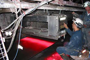
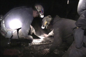
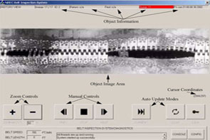
Sweep Monitoring System
- OVERVIEW
NREC developed the Sweep Monitoring System (SMS) for training soldiers and demining personnel to use hand-held land mine detectors. The SMS is now in production.
Land mines remain a hidden, lethal menace for years after they have been laid. Detecting and removing them is a lengthy, dangerous, and labor-intensive process. Effective training in land mine removal saves the lives of military personnel and civilians.
The SMS tracks the movement of a hand-held land mine detection wand and gives immediate feedback to both instructor and trainee on the trainee’s progress. It provides an objective measurement of a trainee’s skill, improving the reliability, safety and accuracy of land mine detection.APPLICATION
The SMS can be used for training on any type of hand-held mine detector wand. It is especially designed for use with the AN/PSS-14 Mine Detection Set, AN/PSS-12 and Minelab F1A4 detectors. Its rugged construction and easy assembly and calibration allow it to be used in a variety of training scenarios both indoors and outdoors. It can be used with either physical or virtual mine arrays. The SMS is currently in use at U.S. Army training centers. It has helped train soldiers for demining work in Afghanistan and other heavily-mined areas. Using the SMS during training has significantly improved trainees’ ability to detect mines with the AN/PSS-14, the Army and Marine Corps’ next generation hand-held land mine detection system.DESCRIPTION
The SMS consists of a pair of stereo cameras that track a target on the head of a demining sensor. The target is a brightly-colored ball that’s mounted on top of the mine detector. As the trainee sweeps the detector across a simulated minefield, the SMS records the position of the target thirty times per second.
From this positional data, the SMS measures a trainee’s performance in areas critical to successful mine detection: sensor head traverse speed, sensor height above ground, coverage area, and gaps in the swept area. This information is shown on a computer display that’s monitored by the training supervisor, giving immediate feedback through color, coverage, and speed vs. height plots.
The SMS also gives real time audio feedback to the trainee, beeping when mines are detected and giving verbal messages (such as "too fast” or "too slow”) about overall performance. This feedback helps to improve the trainee’s skill at detecting mines.
At the end of each session, the SMS summarizes the trainee’s performance in terms of coverage rate, covered area and mine target location. Data recorded during training sessions can be saved and reviewed later.
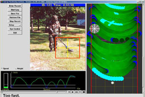
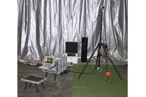
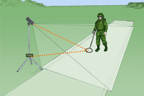
Vision-Based Vehicle Classifier
- OVERVIEW
NREC is developing a vision-based vehicle classifier that will be used in driver assistance systems for automobiles and other mass-market vehicles.
Continental Automotive is building driver assistance systems to help drivers safely change lanes, merge, avoid obstacles, and perform similar maneuvers. NREC’s vehicle classifier will be part of Continental’s future active safety systems. The camera from this system scans the road ahead, looking for other vehicles. NREC's classifier examines these images and uses highly efficient machine learning techniques to quickly and efficiently find areas that
contain vehicles.APPLICATION
An aging population and a growing number of vehicles on the roads are behind the development of driver assistance and other vehicle safety products. Intelligent assistance systems that sense a car or truck’s surroundings and provide feedback to the driver can help to prevent accidents before they happen and will make driving safer, easier, and less tiring.
Current driver assistance systems use vision, ladar, or radar to perceive the vehicle’s environment. However, these sensors all have drawbacks. Radar-based systems detect the proximity of other vehicles but do not give a detailed picture of the surroundings. Ladar-based systems also detect proximity but may not work well in bad weather. Vision-based systems provide detailed information, but processing and interpreting images in the short time frame needed to make driving decisions is challenging.
Continental Automotive Systems is developing vision-based driver assistance systems to help drivers avoid accidents. Continental is drawing upon NREC’s expertise in machine vision and machine learning to develop a classifier that quickly and efficiently detects the presence of other vehicles on the road. NREC’s vehicle classifier is designed to identify and locate vehicles in real-time video images from the lane departure warning system’s camera.DESCRIPTION
The vehicle classifier uses a fast, computationally efficient classification algorithm to identify which images contain vehicles and which ones do not. It is designed to be run on an inexpensive digital signal processor (DSP) that is slightly less powerful than a Pentium 4. Its input is video from the lane departure warning system’s camera, located behind the driver’s rearview mirror.
The classification algorithm is trained on a data set that contains video images of roads with cars, trucks and other vehicles. The locations of each vehicle are labeled by hand in every video frame of the training data set. From this data set, the algorithm learns which image features represent other vehicles and which ones do not. NREC has developed algorithms which reduce the training time by over an order of magnitude from previously published results.
The classification algorithm scans raw incoming images to identify regions in the image that contain cars. An important characteristic of this algorithm is that it works extremely quickly, allowing large regions of the image to be processed at the video frame rate.
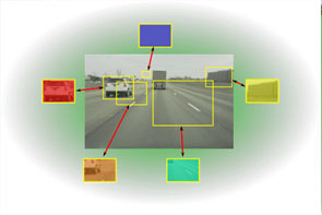
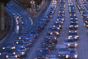
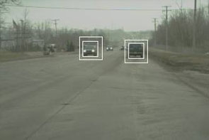
Machine Learning Applications
- We apply state-of-the-art machine learning techniques
in some of our projects, when appropriate, to accelerate development and
improve performance while maintaining quality and reliability. The following
projects all benefited from our world-class machine learning expertise:
- Autonomous Loading System
- UGCV PerceptOR Integration (UPI)
- Urban Challenge
- Vehicle Safeguarding
- Vision-based Vehicle Classifier
Operator Assist Technologies
UPI Teleoperation System
- OVERVIEW
NREC has developed an immersive teleoperation system that allows operators to remotely drive an unmanned ground vehicle (UGV) more effectively over complex terrain.
The United States Army’s Future Combat Systems (FCS) program is developing autonomous UGVs for use in military missions. These missions are classic examples of "triple D” – dirty, dull and dangerous. Automating them will save lives and allow the Army to better carry out its essential tasks. However, full robotic autonomy is not yet at the point where it can be used on the battlefield. Human intervention is still necessary to successfully make use of UGVs under real-world conditions.
Teleoperation allows a human operator to remotely control a UGV. During tactical missions, UGV must maneuver at high speeds and may range far from the operator. The poor situational awareness that current teleoperation systems provide makes it nearly impossible to maintain the pace of operations (optempo) needed to successfully perform tactical missions. By developing more effective teleoperation systems, the military can reap the benefits of using unmanned systems without having to wait for breakthroughs in autonomy.
NREC is developing an immersive teleoperation system as part of the UPI program (UGCV-PerceptOR Integration). NREC’s teleoperation system has been tested on the Crusher UGV under a wide variety of driving conditions. This testing has quantified factors that affect a remote operator’s ability to drive quickly and safely in challenging off-road environments.
APPLICATION
The United States Army has set an ambitious goal of having one third of its ground vehicles be unmanned by the year 2015. Recent successes in deploying scouting and bomb disposal robots have demonstrated practical uses for unmanned systems and encouraged their development and deployment for a wider range of tactical missions.
However, the unmanned ground vehicles (UGVs) that have been deployed so far require teleoperation (remote operation by a human being). Despite recent developments in autonomy, autonomous vehicles still require human intervention. Effective teleoperation is therefore crucial to their successful use.
For teleoperation to work, operators need situational awareness of the UGV’s surroundings. Once an operator takes active remote control of a UGV, it can take minutes to assess the vehicle’s environment and decide what to do next. Providing good visual and physical feedback to the operator improves the operator’s situational awareness and allows the UGV to be operated more effectively.
NREC’s immersive teleoperation system makes operators feel as if they’re actually riding in the vehicle. Field tests of the teleoperation system found tradeoffs between operator performance and parameters like bandwidth, latency, field of view, and video frame rate. Identifying key parameters for successful teleoperation allows the operator to make the most efficient use of the limited data bandwidth between the vehicle and the operator control station.DESCRIPTION
The teleoperation system has four components:- A sensor system mounted on Crusher. It included a high-resolution video camera system and a microphone to pick up sounds in the environment. The camera array consisted of five video cameras, each with a resolution of 1600 x 1200 pixels. These cameras gave the operator a 202 degree by 31 degree field of view.
- A fiber-optic data link between Crusher and the operator station. A kilometer of fiber-optic cable was mounted on a spooler and laid behind the vehicle as it was driven along the test courses. Under ordinary operating conditions, a wireless data link would be used instead of a fiber-optic tether. However, fiber-optic cable was used during testing to provide greater bandwidth.
- A software control system that provided near real-time processing of video images from the camera system. It corrected the video images and controlled their frame rate, resolution, field of view, and other video parameters. It also controlled the operator’s five-screen video display system.
- A control booth that provided visual and vestibular feedback to the driver. Crusher was driven from the operator control booth. Five high-resolution display screens surrounded the driver, each showing an image from one of the vehicle cameras. This gave the driver an immersive, wide angle view of the vehicle’s surroundings. Speakers played noises from the vehicle’s environment. The booth was mounted on a motion base that tracked Crusher’s motion. This gave the driver a physical sense of the vehicle’s movement to complement visual and audio from the vehicle.
Soldier Awareness through Colorized Ranging (SACR)
- OVERVIEW
NREC developed a real-time 3D video system to improve situation awareness in teleoperation and indirect driving.
SACR (Soldier Awareness through Colorized Ranging) fuses video images and ladar in real time to create highly realistic 3D video. Drivers can zoom and pan this wide angle 3D view of the vehicle’s environment. They can shift the virtual camera’s viewpoint to different points around the vehicle – including a synthetic overhead view – to better see its surroundings. Drivers inside vehicles can “see” through the hull. Remote drivers can have a perpetual synthetic line of sight, as if following behind the teleoperated vehicle on foot or in an aircraft. Maps and autonomy plots can be overlaid on the image.
These improvements give drivers a better view of a vehicle’s surroundings, improving their awareness of its environment and making remote and indirect driving safer, easier, and faster. Other potential SACR applications include mapping, mission visualization, mission rehearsal, and localization of personnel and vehicles.
In field trials, operators performed 20% to 50% better on a range of driving tasks with SACR than they did with existing 2D video systems.APPLICATION
Poor situation awareness makes indirect driving (where a driver is sealed inside a windowless vehicle for protection) and remote driving (where a driver teleoperates an unmanned vehicle) more difficult. In both, drivers rely on video cameras that have a limited field of view, display conflicting or confusing images, and cannot show an external view of the vehicle. This limits vehicle speed and contributes to accidents.
Drivers need to know what is going on in the vehicle’s environment and to be able to predict what will happen next. However, this is hard to do without being able to see around the entire vehicle. It can take minutes for a driver to become adequately aware of a teleoperated UGV’s surroundings – time that he or she may not have during a mission!
SACR (Soldier Awareness through Colorized Ranging) uses 3D video to improve a driver’s awareness of the environment. It provides several features that assist indirect and remote driving:- A geometrically correct “virtual driver’s windshield” can be shifted to different points around the vehicle. This makes it easier to view the outside the vehicle and compensates for a driver’s offset from the sensor’s physical location.
- Widening the field of view allows the driver to see more of the vehicle’s surroundings at a glance.
- Drivers can zoom into and out of images to better see points of interest and even “fly around” the outside of the vehicle. An overhead view is especially useful for teleoperating UGVs (similar to driving a radio-controlled toy car).
- Video memory allows the camera to “see through” the vehicle, showing areas that would ordinarily be blocked by parts of the vehicle. This is especially useful for seeing the ground immediately in front of, underneath, or in back of the vehicle – none of which are easily observable from fixed-mount cameras.
- One 3D video feed can produce multiple views for multiple operators.
- Maps, autonomy plots, and other mission-critical information can be superimposed on the 3D video image.
DESCRIPTION
Sensors
The SACR sensor pod includes a high-definition video camera and laser range finder. One or more sensor pods can be mounted on a vehicle.
3D Video
SACR fuses video and range input from the sensor pods in real time to build a 3D computer graphics model of the vehicle’s surroundings.
Underground Mining Operator Assist
- OVERVIEW
NREC’s Underground Mining Operator Assist project improves safety and increases productivity in the underground mining industry.
NREC applied robotic sensors to the development of semi-automated continuous mining machines and other underground mining equipment. Sensors mounted on the mining equipment can accurately measure the machine's position, orientation and motion. These sensors will assist operators standing at a safe distance to precisely control the machine.APPLICATION
The Problem
The U.S. is a world leader in coal production, but profits are squeezed continually. Utility deregulation presses prices down while smaller and shorter seams limit productivity while increasing the costs of mining. Poor visibility underground limits efficiency, as do requisite safety precautions, which nevertheless fail to prevent accidents, injuries and fatalities.
The Solution
NREC, in collaboration with partners NASA and Joy Mining Machinery, developed robotic systems for semi-automating continuous miners and other equipment used for underground mining.
NREC mounted sensors on a Joy continuous miner to accurately measure the machine’s position, orientation, and motion. These sensors assist operators standing at a safe distance to precisely control the machine. Increases in operating precision increases productivity in underground coal mining and decreases the health and safety hazards to mining workers.DESCRIPTION
The NREC development team developed two beta systems to improve equipment positioning, including:- A product to measure the sump depth of a continuous mining machine without the use of external infrastructure. This product is useful for matching the volume of cut coal with the capacity of the haulage vehicles and for increasing productivity via faster sequencing of mining operations.
- A global heading measurement product using a laser reference to cut a straight entry. This product helps eliminate trim cuts, reduces extra roof bolts, and increases productivity via accelerated sequencing.
In above-ground tests, the team demonstrated the ability to measure sump depth with no more error than two percent of distance traveled. The team also demonstrated the ability to track the laser reference to within one centimeter lateral offset and 1/3 degree heading error.
Following the above-ground tests, the team conducted underground testing at Cumberland mine in Pennsylvania and Rend Lake mine in Illinois. More extensive underground testing continued as part of a DoE-FETC-funded program that added DoE INEEL and CONSOL as partners.
Vehicle Safeguarding
- OVERVIEW
NREC designed, developed and tested a fully autonomous system capable of following pre-taught paths while detecting and avoiding obstacles.
Being able to detect obstacles and terrain hazards significantly increases the safety of both manned and unmanned agricultural vehicles. The project uses machine learning techniques and sensor fusion to build a robust obstacle detection system that can be easily adapted to different environments and operating conditions.APPLICATION
The Problem
Agricultural equipment is involved in a significant number of accidents each year, often resulting in serious injuries or death. Most of these accidents are due to operator error, and could be prevented if the operator could be warned about hazards in the vehicle’s path or operating environment.
At the same time, full automation is only a few steps away in agriculture. John Deere has had great success in commercializing AutoTrac, a John Deere developed automatic steering system based on GPS positioning. AutoTrac is currently sold as an operator-assist product, and does not have any obstacle detection capabilities. Adding machine awareness provides safeguarding to a product like AutoTrac, for example, that would be a significant enabler to full vehicle automation.
Any perception system that is used for safeguarding in this domain should have a very high probability of detecting hazards and a low false alarm rate that does not significantly impact the productivity of the machine.The Solution
The NREC developed a perception system based on multiple sensing modalities (color, infrared and range data) that can be adapted easily to the different environments and operating conditions to which agricultural equipment is exposed.
We have chosen to detect obstacles and hazards based on color and infrared imagery, together with range data from laser range finders. These sensing modalities are complementary and have different failure modes. By fusing the information produced by all the sensors, the robustness of the overall system is significantly improved beyond the capabilities of individual perception sensors.
An important design choice was to embed modern machine learning techniques in several modules of our perception system. This makes it possible to quickly adapt the system to new environments and new types of operations, which is important for the environmental complexity of the agricultural domain.DESCRIPTION
In order to achieve the high degree of reliability required of the perception system, we have chosen our sensors so that they provide complementary information that can be exploited by our higher level reasoning systems. To correctly fuse information from the cameras, the laser range finders and the position estimation system we have developed precise multi-sensor calibration and time synchronization procedures.
We implemented feature extractors that analyze the images in real time and extract color, texture and infrared information that is combined with the range estimates from the laser in order to build accurate maps of the operating environment of the system.
Since our perception system had to be easily adaptable to new environments and operating conditions, hard coded rule-based systems were not applicable to the obstacle detection problems we were analyzing. As a result, we developed machine learning for classifying the area around the vehicle in several different classes of interest such as obstacle vs. non-obstacle or solid vs. compressible. Novel algorithms were developed for incorporating smoothness constraints in the process of estimating the height of the weight supporting surface in the presence of vegetation, and for efficiently training our learning algorithms from very large data sets.
The initial system, installed on the 6410 John Deere tractor, has been demonstrated in several field tests. We are currently focusing on a small stand-alone perception system that uses cheaper sensors and could potentially by used as an add-on module for several existing types of agricultural machinery.
Vehicle Stability Prediction
- OVERVIEW
NREC has developed an easy-to-implement solution to an important problem — stability margin estimation as it relates to vehicular rollover and tipover vulnerabilities.
A concrete realization of a stability margin estimation system for real-world applications has not existed until now. NREC scientists and engineers developed a real-world, effective system to prevent maneuver-induced rollover and tipover.
NREC’s Stability Prediction System (SPS) calculates the effects of lateral acceleration and gravity as either curvature, speed, or slope increase, and when state of motion approaches a tipover condition, the system recognizes the situation and stabilizes the vehicle.APPLICATION
The Problem
For vehicles operating on slopes, the inherently "reduced stability margin” significantly increases the likelihood of rollover or tipover.
Unmanned ground vehicles (UGVs) are not the only wheeled vehicles that traverse rough terrain and steep slopes. Contemporary, driver-operated mining, forestry, agriculture and military vehicles do so, as well, and frequently at high speeds over extended periods of time. Cranes, excavators and other machines that lift heavy loads also are subject to dramatically increased instability when operating on slopes. Slopes are only one factor to consider. Preventing vehicular tipover on flat surfaces (inside a warehouse, for example) is just as important, especially when considering that market forces reward manufacturers of lift trucks that are smaller, lift heavier loads and lift those loads higher than could be done previously.
The Solution
NREC experts devised a solution featuring a combination of sophisticated software and hardware, including inertial sensors and an inclinometer-type pendulum at the vehicle’s center of gravity.
During vehicular operation, the system continuously and actively calculates stability margin measurements to trigger an alarm, drive a "governor” device or alter the suspension. It calculates lateral acceleration as either curvature or speed increase. When state-of-motion activity reaches rollover / tipover vulnerability, the system recognizes the situation and triggers the desired action.
This system can be deployed on robotic and driver-operated vehicles (including cars) and machinery (cranes, excavators, lift trucks, pallet jacks, etc.).DESCRIPTION
NREC researchers developed algorithms for a stability margin estimation system. These algorithms take into account diverse variables such as the aggregate effect of gravity and changing kinematic forces. NREC scientists then developed animated simulations to test models for maneuver-based stability of vehicles and machinery (lift trucks, excavators, cranes, etc.) at various slopes, speeds and payload articulations.
Further testing involved the use of test-bed hardware, including a lift truck. The lift truck underwent major retrofitting to incorporate sensors, (gyro, axis accelerometer and inclinometer), stabilizing equipment, computer hardware and control software. As part of the hardware platform, NREC created a data logger system for use in simulation scenarios. NREC testers calibrated the models used in simulation to minimize risk of tipover of the actual test vehicles.
The sensing/driver control system was developed in Matlab/Simulink and included models for inertial sensors and a user interface to simulate input driver commands to the lift truck, including steer, speed, lift height, side-shift and tilt. Furthermore, a software interface layer was defined to connect the stability-prediction algorithms to the sensing system. Through the driver control interface, the user can input drive commands to the truck, which results in the dynamic model responding to these commands. As the vehicle executes the user commands, the sensing system monitors vehicle stability.
Autonomous Vehicle Technologies
UGCV PerceptOR Integration (UPI)
- OVERVIEW
The UPI program builds upon the success of UGCV and PerceptOR to improve the speed, reliability, and autonomy of unmanned ground vehicles.
UPI combines the mobility and ruggedness of the Crusher vehicles with advanced perception, autonomy and learning techniques. The program stresses system design across vehicles, sensors and software, so that each component’s strengths compensates for another’s weakness.
As a Future Combat Systems (FCS) technology feed program, the UPI program’s results are advancing work on other autonomous vehicle programs including the Armed Reconnaissance Vehicle (ARV) and the Autonomous Navigation System. (ANS).APPLICATION
The Problem
Navigating complex terrain at speed and with minimal human supervision has always been a major challenge for UGVs. The need to recognize obstacles requires a dramatic improvement in perception capability. Also, the continued likelihood of running into obstacles requires a vehicle that is rugged enough to continue operating after sustaining tolerable damage in collisions.
The Solution
Building on successful results from PerceptOR, the UPI program’s perception and automation systems are being extended to improve automation capabilities at higher speeds.
As part of UPI, NREC designed a new vehicle, Crusher, which features a new highly durable hull, increased travel suspensions, and leverage off many development and improvements from the Spinner vehicle.
Enhanced perception capabilities include new "learning” technologies that enable the vehicle to learn from terrain data. It can then navigate new, highly varied terrains with increasing levels of autonomy. The team is also applying machine learning techniques to improve Crusher ’s localization estimate in the absence of GPS.
Payload development, integration and testing are scheduled to continue through 2008. UPI will bring together technologies and people to produce autonomous vehicle platforms capable of conducting missions with minimal intervention.DESCRIPTION
With the addition of two new vehicles, the program will be able to conduct three parallel field testing agendas in varied terrain sites:- Building on successful results from PerceptOR, the perception and automation systems will be extended to provide improved automation capabilities at higher speeds. Increased focus will be placed on the use of prior overhead data as well as learning technologies which will allow the vehicle to move effectively through previously untraveled terrains. Technologies that can supervise or support off-road navigation in highly varying terrain will be a priority.
- Vehicle field testing will continue, allowing for continuous improvement of obstacle capability, resilience, endurance, and payload fraction (key goals for UGVs). Vehicle performance will be analyzed, modified, and tested continuously to maximize the inherent terrainability of the Crusher platform.
- Payload development, integration and testing will prove out the intended mission scenarios. Leveraging upon unmanned vehicle capabilities and Crusner's unique terrain capabilities, these field tests will help demonstrate and influence the use of autonomous vehicles in the future.
Urban Challenge
- OVERVIEW
Carnegie Mellon University and General Motors built an autonomous SUV that won first place in the 2007 DARPA Urban Challenge.
The Urban Challenge race was held on November 3, 2007 at the Victorville training facility in California. Eleven teams competed against each other to finish a 60-mile city course in less than six hours. Their vehicles had to conduct simulated missions in a mock urban area while obeying traffic laws, safely merging into moving traffic, navigating traffic circles, negotiating busy intersections, and avoiding other vehicles – all without human intervention.
Carnegie Mellon’s “Boss” (an autonomous Chevy Tahoe named after legendary General Motors engineer Charles “Boss” Kettering) was the first of three vehicles that actually finished the race within the six-hour time limit. Three other entries finished after the time limit had expired.
Carnegie Mellon’s Tartan Racing team was led by internationally-recognized mobile robotics expert Red Whittaker and key members of Red Team Racing, who fielded strong entries in the 2004 and 2005 DARPA Grand Challenge races. Faculty and staff from across the university, including Tony Stentz, Alonzo Kelly and Drew Bagnell from the National Robotics Engineering Center, joined Tartan Racing’s drive to win the Urban Challenge. General Motors, Caterpillar, Continental and other partners brought their vehicle development and engineering expertise to the Urban Challenge.APPLICATION
The 60-mile Urban Challenge course wound through an urban area with crowded streets, buildings, traffic, road signs, lane markers, and stop lights. The exact route was unknown until the morning of the race. Each vehicle attempted to complete a series of three missions within a six-hour time limit. No human intervention whatsoever was allowed during the race. Each vehicle used its on-board sensing and reasoning capabilities to drive safely in traffic, plan routes through busy streets, negotiate intersections and traffic circles, obey speed limits and other traffic laws, and avoid stationary and moving obstacles – including other Urban Challenge competitors.
Tartan Racing entered the Urban Challenge to bring intelligent autonomous driving from the pages of science fiction to the streets of your town. The technologies developed for this race will lay the groundwork for safer, more efficient, and more accessible transportation for everyone.
An aging population and infrastructure and rising traffic volumes put motorists at risk. Without technological innovation, auto accidents will become the third-leading cause of death by 2020. Integrated, autonomous driver assistance systems and related safety technologies will prevent accidents and injuries and save lives. They will also help people retain their freedom of movement and independence as they grow older.
Autonomous driving technologies can also be used to improve workplace safety and productivity. Assistance systems for heavy machinery and trucks will allow them to operate more efficiently and with less risk to drivers and bystanders.DESCRIPTION
Tartan Racing took a multi-pronged approach to the daunting challenge of navigating the dynamic environment of a city:- Organize and orchestrate concurrent software components to determine
sequences of tasks, process sensor data, and control the vehicle.
Response times had to be less than a second! Other software components
continuously monitored the status of individual tasks to find out
whether they were
successfully completed. - Sense, differentiate and localize objects (such as buildings and cars) and environmental features (such as lane markings, curbs, and sidewalks), both fixed and moving. The vehicle used radar, ladar, and video sensors to perceive its environment and GPS and IMUs to establish its position.
- Control actuators to ensure safe and efficient driving in intersections, parking lots, traffic circles, and similar city features.
- Plan and replan the most efficient routes through a network of streets, taking into account constantly-changing conditions.
- Retrofit two stock Chevy Tahoe SUVs to enable computer control of their steering, speed and gears.
- Achieve robustness by applying well-known principles of systems engineering and testing, using both simulation and live tests. The goal was to make the vehicles as reliable as possible for the race.
NREC faculty and staff took on key leadership roles in conquering these technical challenges.
- Organize and orchestrate concurrent software components to determine
sequences of tasks, process sensor data, and control the vehicle.
Response times had to be less than a second! Other software components
continuously monitored the status of individual tasks to find out
whether they were
Automated Material Transport System
- OVERVIEW
NREC developed AMTS, an innovative system for accurately guiding robotic material transport vehicles in industrial settings.
AMTS uses robotic lift trucks to automate the transfer of pallets and other materials from semi-trailers onto robotic tugs for transport in factories and warehouses. It makes use of a sophisticated downward computer vision system and LADAR range finders to direct and control these vehicles as they load and unload material and transport it across the factory floor.
AMTS’s lower-cost, infrastructure-free automation system decreases human involvement in setting up and operating material transport systems. It makes automated loading and unloading of over-the-road trailers more feasible and cost-effective.APPLICATION
The Problem
Until the scientists and engineers at NREC developed the AMTS solution, companies had limited options to relying on driver-operated forklifts and tug vehicles for transporting materials and stacking pallets in factories and warehouses.
Current automated guided vehicles (AGVs) are limited by their inability to "see” their surroundings. And, in order to function at all, they required complex setup and costly changes to facility infrastructure. For example, companies using conventional AGVs have to install special sensors, jigs and attachments for an automated forklift to pick up a pallet of materials.
The Solution
NREC scientists and engineers devised a computer vision system that can be used with any mobile robot application. Today’s cost-effective AMTS solution works effectively around the clock, with lights out in many cases and with less damage to vehicles than humans cause. There is typically no need to retrofit the facility infrastructure to accommodate the AGVs. These AMTS-equipped automated vehicles — robotic forklifts and tugs — find their way around by virtue of a low-cost, high-speed positioning system developed at NREC.
NREC equips each vehicle with a combination of cameras and laser rangefinders for navigation and control. With a downward-looking camera mounted to the bottom of the forklift, the robot captures visual cues and matches them to a pre-stored database of floor imagery that becomes its map for navigating the floor.
Using a forward-looking camera system, the forklift images the side of the trailer to find pallets for transfer to tug vehicle wagons. The forks are inserted into the pallet holes, and the forklift lifts the pallet. While it is backing out of the trailer, the robotic forklift relies on its laser rangefinder to safety remove the tight-fitting pallet from the trailer. The robotic tug vehicle uses the same downward vision technology to move around and position its wagons for loading and unloading.DESCRIPTION
NREC scientists and engineers developed four novel vision systems and associated visual servoing control systems, as well as factory-level vehicle traffic coordination software.
Development of the AMTS solution began with prototypes of both the position-estimation technology and pallet-acquisition vision system. After integrating NASA technology into these systems, NREC provided a demonstration of simplified, automated trailer loading/unloading and automated pallet stacking.
Subsequently, during an AGV pilot program at an automotive assembly plant, several tug AGVs used the AMTS downward vision technology and proved its viability.
Today, the AMTS is available as a pragmatic solution for efficient, cost-effective materials transport in manufacturing facilities, industrial plants and storage warehouses. Because it requires no changes to facility infrastructure, it makes automated materials handling more practical and affordable than ever before.
Black Knight
- OVERVIEW
The National Robotics Engineering Center (NREC) developed sensing, teleoperation and autonomy packages for BAE Systems' Black Knight, a prototype unmanned ground combat vehicle (UGCV).
Black Knight demonstrates how UGCVs can be used in the field and showcases current robotics technologies. NREC applied its expertise in sensor fusion, unmanned systems, obstacle detection, path planning, autonomy and teleoperation to improve Black Knight's mission performance and support Soldier operation.APPLICATION
Black Knight can be used day or night for missions that are too risky for a manned ground vehicle (including forward scouting, reconnaissance surveillance and target acquisition, (RSTA), intelligence gathering, and investigating hazardous areas) and can be integrated with existing manned and unmanned systems. It enables operators to acquire situational data from unmanned forward positions and verify mission plans by using map data to confirm terrain assumptions.
Black Knight demonstrates the advanced capabilities that are available to unmanned ground combat vehicles (UGCVs) using current technology. Its 300 hp diesel engine gives it the power to reach speeds of up to 48 mph, with off-road autonomous and teleoperation speeds up to 15 mph. Its band-tracked drive makes it highly mobile in extreme off-road terrain while reducing its acoustic and thermal signatures. The 12-ton Black Knight can be transported within a C-130 cargo plane and makes extensive use of components from the Bradley Combat Systems program to reduce costs and simplify maintenance.
Black Knight can be teleoperated from within another vehicle (for example, from the commander's station of a Bradley Fighting Vehicle) or by dismounted Soldiers. Its Robotic Operator Control Station (ROCS) provides an easy-to-use interface for teleoperating the vehicle. Black Knight's autonomous and semi-autonomous capabilities help its operators to plan efficient paths, avoid obstacles and terrain hazards, and navigate from waypoint to waypoint. Assisted teleoperation combines human driving with autonomous safeguarding.
Black Knight was extensively tested both off-road and on-road in the Air Assault Expeditionary Force (AAEF) Spiral D field exercises in 2007, where it successfully performed forward observation missions and other tasks. Black Knight gave Soldiers a major advantage during both day and night operations. The vehicle did not miss a single day of operation in over 200 hours of constant usage.DESCRIPTION
NREC developed Black Knight's vehicle controller, tele-operation, perception and safety systems.
Black Knight's perception and control module includes Laser Radar (LADAR), high-sensitivity stereo video cameras, FLIR thermal imaging camera, and GPS. With its wireless data link, the sensor suite supports both fully-autonomous and assisted (or semi-autonomous) driving.
Black Knight's autonomous navigation features include fully-automated route planning and mission planning capabilities. It can plan routes between waypoints – either direct, straight-line paths or paths with the lowest terrain cost (that is, the lowest risk to the vehicle). Black Knight's perception system fuses LADAR range data and camera images to detect both positive and negative obstacles in its surroundings, enabling its autonomous navigation system to avoid them.
These autonomy capabilities can also assist Black Knight's driver during teleoperation. Black Knight can plan paths to be manually driven by its operator. In “guarded teleoperation” mode, objects that are detected by the perception system are overlaid on the driving map, enabling drivers to maneuver around them. The vehicle also stops when it detects lethal obstacles in its path. Black Knight is driven from the Robotic Operator Control Station (ROCS), located within another vehicle. It can also be driven off-board via its safety controller. The ROCS displays images from the vehicle's color and FLIR driving cameras and includes a hand controller for steering the vehicle and operating its sensors. It also allows the driver to control and view the status of the various vehicle and sensor systems. Map and route displays help the driver to navigate through unfamiliar terrain.
The ROCS also allows operators to control the Commander's Independent View (CIV) sensor suite. The CIV is used for remote surveillance and target acquisition (RSTA) and includes color video and FLIR cameras.
Autonomous Loading System
- OVERVIEW
NREC developed ALS, which completely automates the task of loading excavated material onto dump trucks.
The ALS robotic excavator is capable of loading trucks at the speed of an expert human operator, increasing productivity and improving the safety of excavation projects.
The excavator uses two scanning LADAR rangefinders to locate the truck, measure the soil face and detect obstacles. The ALS software decides where to dig in the soil, where to dump the excavated soil in the truck, and how to quickly move between these points while detecting and stopping for obstacles. The system modifies both its digging and dumping plans based on soil settling detected by its sensors.APPLICATION
The Problem
Surface mining of metals, quarrying of rock, and construction of highways requires the efficient removal of massive quantities of soil, ore, and rock. Human-operated excavators load the material into trucks. Each truckload typically requires several passes, each of which in turn takes 15–20 seconds. The operator’s performance peaks early in the work shift but wears down with fatigue. Scheduled idle times, such as lunch and other breaks, also diminish production across a shift.
Safety is another important consideration. Excavator operators are most likely to be injured when mounting or dismounting the machine. Operators tend to focus on the task at hand and may fail to notice other site personnel or equipment entering the loading zone.The Solution
Automating the excavation and loading process would increase productivity and improve safety by removing the operator from the machine and by providing complete sensor coverage to watch for potential hazards entering the work area.
Recognizing this opportunity, NREC scientists and engineers developed a system that completely automates the truck loading process.DESCRIPTION
In designing the ALS and conducting experimental trials, the ALS team used a combination of hardware, software and algorithms for perception, planning and control.
The ALS hardware subsystem consists of the servo-controlled excavator, on-board computing system, perception sensors and associated electronics. During development of the system, the NREC team developed a laser-based scanning system that would be able to penetrate a reasonable amount of dust and smoke in the air. Additionally, the team developed two different time-of-flight scanning ladar systems that are impervious to ambient dust conditions.
The NREC team designed the software subsystem with several modules to process sensor data, recognize the truck, select digging and dumping locations, move the excavator’s joints, and guard against collision.
Planning and control algorithms decide how to work the dig face, deposit material in the truck, and move the bucket between the two. Perception algorithms process the sensor data and provide information about the work environment to the system’s planning algorithms.
Expert operator knowledge was encoded into templates called scripts, which were adjusted using simple kinematic and dynamic rules to generate very fast machine motions. The system was fully implemented and demonstrated on a 25-ton hydraulic excavator and succeeded in loading trucks at about 80% of the speed of an expert human operator.
LAGR Robot Platform
- OVERVIEW
DARPA needed to supply a standard, mobile robot platform to research teams performing on the Learning Applied to Ground Robots (LAGR) program. NREC designed, built and delivered 12 turnkey robots in seven months to support the LAGR kick-off meeting.
The LAGR robot includes all the necessary hardware, sensing and software for autonomous operation indoors or outdoors. Its well documented application program interface (API) and modular design allows for partial or total swap of the autonomy software modules with the owner’s software.
A developer-friendly design features long battery life, standard development environment, extensive data logging capabilities, and system simulator.
Today, NREC supports more than a dozen customers and 30 fielded robots. NREC provides remote technical support, spare parts supply and user training.APPLICATION
The goal of the LAGR program is to develop a new generation of learned perception and control algorithms that will address the shortcomings of current robotic ground vehicle autonomous navigation systems through an emphasis on learned autonomous navigation. DARPA wanted the ten independent research teams they selected to immediately focus on algorithm development rather than be consumed early in the project with getting a baseline robotic platform working. DARPA also wanted a common platform so that software could be easily shared between teams and so that the government could make an objective evaluation of team results.
In just seven months, NREC designed and then built 12 LAGR robots which allowed DARPA to hold the LAGR kick-off meeting on time and to provide each research team with a fully functional autonomous platform for development.
Teams were given 4 hours of training at kick-off and were able to program basic obstacle avoidance capability the same day. Developers were able to focus immediately on learning algorithm research because all basic autonomy capabilities along with well documented APIs were provided with delivery.
Careful configuration control for all platforms enables developers to develop software at their home station, load their software on a memory stick, and ship the memory stick to DARPA, which then runs the software on their LAGR robot.DESCRIPTION
The LAGR robot includes three 2.0 GHz Pentium-M computers, stereo cameras, IR rangefinders, GPS, IMU, encoders, wireless communications link, and operator control unit. NREC ported its PerceptOR software to the platform to provide baseline autonomous capability.
Communications tools include Gigabit Ethernet for on-board communication; a wireless (802.11b) Ethernet communications link; remote monitoring software that can be run on a laptop; and a standalone radio frequency remote.
The user can log data on the robot in three different modes: teleoperation using the RF remote; teleoperation from the onboard computer system (OCS); and during autonomous operation.
With each robot, NREC ships a comprehensive user manual that documents robot capability, baseline autonomy software, and APIs (with examples) that enable developers to easily interface robot sensor data to their perception and planning algorithms.
Autonomous Spraying
- OVERVIEW
NREC converted a John Deere tractor into an autonomous vehicle for spraying water in orchards.
NREC developed a vehicle retrofit kit that allowed the tractor to operate without a human driver. Its software accurately estimated the vehicle’s position and enabled it to autonomously follow previously-driven paths.
The autonomous tractor sprayed water while following a seven kilometer long path through an orange orchard without any human intervention.APPLICATION
The Problem
Crop spraying is inherently hazardous for the operators that drive spraying equipment. Removing the driver from the machine would lead to increased safety and reductions in health insurance costs. Furthermore, if a system can support nighttime operations less chemical needs to be sprayed for the same effect, due to increased bug activity. This results in higher quality crops and reduced spraying expenses.
The Solution
The NREC developed an unmanned tractor that can be used for several agricultural operations, including spraying. The system uses a GPS receiver, wheel encoders, a ground speed radar unit and an inertial measurement unit (IMU) in order to precisely record and track a path through a field or an orchard. The NREC team mounted two color cameras on the vehicle, to enable the use of color and range based obstacle detection.
The teach/playback system was tested in a Florida orange grove, and it sprayed autonomously while following a path of 7km at speeds ranging between 5 and 8 km/h.DESCRIPTION
The initial focus of the project was the design of the retrofit kit for converting the 6410 tractor to an autonomous vehicle. One of the key requirements was that after the retrofit the vehicle is still drivable by a human like a normal tractor, in order to facilitate the path recording process. Since the vehicle was not drive-by-wire, the NREC developed actuators for braking, steering and speed control.
To achieve the path teach/playback capability, NREC developed a positioning system that uses an extended Kalman Filter for fusing the odometry, the GPS information and the IMU measurements. The path following system is based on the Pure Pursuit algorithm. More information about the performance of the system can be found in our "Autonomous Robots” paper.
Robotics Simulation Support
- OVERVIEW
NREC is collaborating with RAND Corporation to incorporate NREC’s field-proven robotic mobility and planning software into RAND’s suite of high-resolution, force-on-force simulators.
To better analyze scenarios involving robotic systems, NREC and RAND added robotic planning, mobility and control algorithms to high-resolution simulation models. NREC's Field D* dynamic planning library has been incorporated into RAND's Janus and Joint Conflict and Analysis Tactical Simulation (JCATS) force-on-force simulation environments. NREC’s fractal terrain generation algorithms (which generate very high-resolution terrain for robotic mobility simulations) and intervisibility algorithms (which determine whether targets are visible to assets and assets are visible to threats) have also been added to the Janus and JCATS simulators.APPLICATION
Most constructive and virtual simulations have very simplified representations of robotic systems, particularly with respect to mobility, target acquisition, interaction, and collaboration. Military simulation planning algorithms often treat robotic vehicles as manned entities with reduced speeds and sensing capabilities. Models seldom incorporate representations for such aspects as autonomous planning, perception, and coordination. Scenarios for examining future applications of ground and air robotic systems tend to focus on manned system missions, with minimal development of uniquely robotic capabilities.
By connecting field-proven NREC robotics technology directly to the simulators, analysts can get higher fidelity simulations of robotic system behavior. This allows for better understanding of the utility and best directions for improvement of those systems. And by closing the loop between robotic system developers like NREC and the users of those systems much faster than ever before, enhancements can be made earlier in the development cycle, and therefore at a lower cost.DESCRIPTION
In the project’s first phase, NREC developed a highly reusable Robotic Simulation Support module to interface the Field D* planner with the Janus Force on Force simulator. Because the base resolution of the Janus terrain was lower than is necessary to accurately simulate robotics behavior, we used a Fractal Terrain Generator to add the appropriate roughness for each terrain type.
To ensure the additions produced by the generator accurately reflected the true difficulty of the terrain; we also developed an easy-to-use GUI-based tool which allows the RAND analysts to adjust the Terrain Generator’s input parameters, ensuring the validity of the simulation. Following development, successful integration tests on relevant simulation scenarios were run at RAND’s facilities.
In the second phase, NREC adapted the software module to connect to the JCATS simulator as well. Again, NREC and RAND successfully tested the integration on relevant simulation scenarios. NREC also began designing a system to bring new cooperative robotic behaviors to the simulator.
Currently, we are working to develop and integrate those behaviors with RAND’s simulators.
PerceptOR
- OVERVIEW
NREC designed, developed and tested an innovative autonomous perception and navigation system for the DARPA PerceptOR program.
The PerceptOR program’s goal was to improve the ability of unmanned ground vehicles (UGVs) to navigate autonomously. NREC was the only organization that participated in all three phases of the program.
The NREC team developed an autonomous UGV that was guided by a small unmanned helicopter (flying eye). The flying eye scouted the terrain ahead of the UGV to detect hazards at long range. The UGV’s extensive onboard sensor suite detected close-range and mid-range hazards and confirmed the existence of obstacles seen from the air. Combining these two sources of terrain data allowed the UGV to plan paths that avoided dangerous areas.
The PerceptOR program’s technology has been transitioned to the UPI, LAGR and ANS programs.APPLICATION
The Problem
Today’s unmanned ground vehicles (UGVs) require constant human oversight and extensive communications resources particularly when traversing complex, cross country terrains. UGVs cannot support tactical military operations in a large scale way until they are able to navigate safely on their own and without constant human supervision. Off all classes of obstacles, UGVs are particularly vulnerable to "negative obstacles" like a hole or a ditch, which are difficult for a ground vehicle to sense due to the limited range and height of on-board sensors.
The Solution
The NREC-led team developed an innovative PerceptOR "Blitz” concept — an integrated air/ground vehicle system that incorporates significant autonomous perception, reasoning and planning for unmanned ground vehicles.
The autonomous UGV included LADAR, three stereo camera pairs, intra- and inter-vehicle sensor fusion, terrain classification, obstacle avoidance, waypoint navigation and dynamic path planning. The unmanned air vehicle — the Flying Eye — views the terrain from above, an optimal vantage point for detecting obstacles such as ruts, ditches and cul de sacs.
The team successfully demonstrated the UGV and Flying Eye working collaboratively to improve navigation performance. The UGV planned its initial route based on all available data and transmitted the route to the Flying Eye. The Flying Eye flew toward a point on this route ahead of the UGV. As the Flying Eye maneuvered, its downward looking sensor detects obstacles on the ground. The location of these obstacles was transmitted back to the UGV in relation to the UGV’s position. The UGV replans its intended path to avoid the obstacles and directs the Flying Eye to scout the new path.
The improved obstacle sensing capabilities (due to dual, well-separated views) and the optimized route planning (enabled by the Flying Eye's reconnaissance) increase the UGV’s autonomous speed by decreasing the risk of the vehicle being disabled or trapped, and by reducing the need for operator intervention and communications system bandwidth.DESCRIPTION
Working in collaboration with its subcontractors, NREC developed the PerceptOR Blitz solution in a three-phase program.
In Phase I, the team developed a vehicle perception system prototype that included three sensing modalities, sensor fusion, terrain classification software, waypoint navigation and path planning software. A commercial ATV, retrofitted for computer control, served as the perception system platform.
In Phase II, the team validated the PerceptOR prototype on unrehearsed courses at test sites spanning four distinctly different types of terrain: sparse woods in Virginia; desert scrub with washes, gullies and ledges in Arizona; mountain slopes with pine forests in California; and dense woods with tall grass and other vegetation in Louisiana. During the test runs, the team demonstrated fully integrated unmanned, air/ground sensing that was used to detect and avoid negative obstacles and other hazards. They also negotiated complex terrain using only passive sensing. Additionally, they classified difficult terrain types (ground cover, meter-high vegetation, desert scrub) by fusing geometric and color sensor data.
In Phase III, the NREC team continues to improve the performance and reliability of the perception system with additional development and field trials. The team advanced UGV autonomous capabilities for operating in sub-optimal conditions, such as with obscurants (dust, smoke or rain), degraded GPS coverage, and reduced communications bandwidth.
Automated Mowing
- OVERVIEW
NREC collaborated with the Toro Company to develop a prototype autonomous mower that can be used in the maintenance of a golf course, sports field or commercial landscape.
NREC scientists and engineers developed a robotic mower that can mow a golf course autonomously, safely and precisely, while sensing and avoiding small obstacles (like golf balls) reliably.
Automated mowing reduces the need for human operators, allowing them to concentrate on other tasks for optimization of labor costs. The system also reduces the need to operate mowers during peak golfing hours, resulting in a more pleasant golfing experience.APPLICATION
The Problem
Golf courses require constant maintenance and routinely bear high labor costs for teams of semi-skilled operators to mow fairways, frequently at peak golfing times. Mower operators must avoid golfers, maintain a neat appearance, combat fatigue and operate the mower safely.
The Solution
NREC’s autonomous mower system meets these demands by providing a system that requires a minimal amount of supervision that can be operated at night and during other off-peak hours.
The autonomous mower has a highly reliable obstacle detection and localization system. NREC developed an obstacle detection system that includes a sweeping laser rangefinder, which builds a 3D map of the area in front of the mower. It "learns” and uses this map to detect obstacles along the way. The robotic mower’s localization system combines GPS and inertial data to provide a position estimate that is accurate and robust.DESCRIPTION
To achieve complete automation on golf courses and sports fields, NREC scientists and engineers developed capabilities for reliable obstacle detection, precise navigation and effective coverage.
Reliable obstacle detection:- NREC designed the system so that it recognizes true obstacles, as small as a golf ball, while not generating false positives, to keep the vehicle safe.
- NREC engineers continue to refine the system so that it will discriminate true obstacles from tall grass.
Precise navigation:
- NREC’s autonomous mower operates with centimeter-level precision to create the cross-hatch patterns seen on premier golf courses.
- NREC robotics engineers continue to refine the system to improve its reliability in areas of minimal GPS coverage.
Effective coverage:
- NREC designed the robotic mower to follow patterns that enable it cover the entire fairway efficiently.
- NREC's software engineers continue to refine the system's interface for enhanced ease-of-use.
Automated Harvesting
- OVERVIEW
NREC produced a new class of robotic harvesters that increase efficiency and productivity in agriculture by reducing reliance on human operators.
The automated harvesting project targeted three levels of automation:- A "cruise control” feature to automatically steer, drive and control the harvesting header, thereby allowing allow the operator to focus on other in-cab controls and harvest conditions.
- A GPS-based "teach/playback” system to enable the harvester to "learn” a field and then repeat a given path, thereby allowing one operator to remotely control several harvesters.
- A fully autonomous harvester using vision perception to completely harvest a field with no human supervision.
APPLICATION
The Problem
Farmers struggle constantly to keep costs down and productivity up. Mechanical harvesters and many other agricultural machines require expert drivers to work effectively. Labor costs and operator fatigue, however, increase expenses and limit the productivity of these machines.
The Solution
In partnership with project sponsors NASA and New Holland, Inc., NREC built the a robotic harvester, which harvests crops to an accuracy of 10cm by using a combination of a software-based teach/playback system and GPS-based satellite positioning techniques. Capable of operating day and night, the robot can harvest crops consistently at speeds and quality exceeding what a human operator can maintain.
Tangible results from extensive field tests conducted in El Centro, California demonstrated that an automated harvester would increase efficiency; reduce cost and produce better crop yield with less effort.DESCRIPTION
For robot positioning and navigation, NREC implemented a differential GPS-based teach/playback system. Differential GPS involves the cooperation of two receivers, one that's stationary and another that's roving around making position measurements. The stationary receiver is the key. It ties all the satellite measurements into a solid local reference.
With the teach/playback system, the Windrower "learns" the field it is cutting, store the path in memory and then is programmed to repeat the path on its own.
Early in the project, the NREC team used color segmentation to determine the cut line for machine servoing. The approach differentiates the percentage of green representing the standing crop and the brown stubble of the cut crop. The system’s computer scans the cut line to determine machine direction. The Windrower is guided at speeds of 4–8 mph to about a 3-inch variance from this crop line.
Other guidance and safety instruments include an inclinometer to protect the machine from rollover and tipover and a gyroscope for redundant guidance.
Autonomous Peat Moss Harvesting
- OVERVIEW
NREC developed an add-on perception system for automating peat moss harvesting.
NREC integrated its add-on perception packages onto a team of three computer-controlled tractors developed by John Deere. These autonomous tractors were used in harvesting operations in a peat bog.
The robotic peat harvesting team was continuously tested for a full season, completing over 100 harvesting missions in a working peat bog. Their behavior imitated manual peat harvesting operations while maintaining a safe operating environment.APPLICATION
Peat moss is commonly used in gardening and plant growing. It is accumulated, partially decayed plant material that is found in bogs. An active peat bog is divided into smaller, rectangular fields that are surrounded by drainage ditches on three sides. When the top layer of peat is dry, the fields are ready to be harvested. Harvesting is done daily, weather permitting.
Peat is harvested with tractor-pulled vacuum harvesters. The vacuum harvesters suck up the top layer of dry peat as they’re pulled across a peat field. When the harvester is full, its operator dumps the harvested peat onto storage piles. The stored peat is later hauled away to be processed and packaged.
Peat moss harvesting is a good candidate for automation for several reasons:- Peat fields have a well-defined, structured environment.
- Peat bogs are largely free of obstacles and vegetation.
- The manual harvesting process lends itself well to automation.
- Peat bogs are located in remote areas, where there are often shortages of qualified operators. This provides an incentive to automate the harvesting process.
DESCRIPTION
NREC’s add-on perception system performs three tasks that are important for safe autonomous operation.
Detecting Peat Storage Piles
Before it can dump the harvested peat onto a storage pile, the robot needs to find the edge of the pile. However, it cannot rely on GPS because the storage piles change shape, size and location as harvested peat is added to them. To locate the edges of storage piles, the perception system finds contiguous areas of high slope in the sensed 3D ground surface. A probabilistic spatial model of the ground surface generates smoothed estimates of ground height and handles sensor noise.Detecting Obstacles
Although peat fields are generally free of obstacles, the harvesters must detect the presence of obstacles such as people, other harvesters, and other vehicles) to ensure safe unmanned operation. To detect different types of objects, the perception system uses a combination of algorithms that make use of 3D ladar data to find dense regions, tall objects, and hot regions above the ground surface.
Detecting Ditches
Ditch locations are mapped with GPS. However, as an added safety precaution, they are also detected by the perception system. The perception system searches for ditch shapes in the smoothed estimate of ground height.
RVCA
- OVERVIEW
NREC is implementing an end-to-end control architecture for unmanned ground vehicles (UGVs) to reduce integration risk in the US Army’s Future Combat Systems (FCS) program.
The Robotic Vehicle Control Architecture (RVCA) program demonstrates whether autonomous UGV operations can be successfully carried out with FCS representative system-of-system hardware and software components. Its rigorous, ongoing field testing unites the powerful Crusher UGV with the advanced capabilities of the Autonomous Navigation System (ANS) and other FCS components.APPLICATION
RVCA provides the following benefits to FCS:- Verifies how ANS functions on a UGV platform
- Assesses UGV control with representative FCS hardware and software components operating within FCS network constraints
- Provides feedback that influences the development of FCS Battle Command software
- Reduces force integration risk for FCS
- Expedites the delivery of unmanned systems to soldiers in the field
DESCRIPTION
RVCA consists of the following:- A UGV platform with integrated ANS hardware and software. Currently, RVCA is using the rugged, highly-mobile Crusher UGV platform. Later in the program, RVCA technology will be integrated onto the APD platform.
- Integrated System of System Common Operating Environment (SOSCOE) in both manned and unmanned vehicle platforms Integrated Vehicle Management System (VMS) and Integrated Computer System (ICS) to control a UGV
- Supporting data for operation of a UGV using these components in a networked environment
Engineering evaluations in the field focus on capabilities such as waypoint following, teleoperation, the system’s overall performance with ANS and other software components, and its use by soldiers in the field. The program concludes in 2010 with a Soldier Operational Experiment.
Innovative Mechanisms
Pipeline Explorer
- OVERVIEW
NREC designed, built and deployed Pipeline Explorer, the first untethered, remotely-controlled robot for inspecting live underground natural gas distribution pipelines.
Explorer represents the state of the art in remote-controlled inspection systems for low-pressure and high-pressure natural gas pipelines. The battery-powered Explorer can perform long-range, extended duration visual inspections of cast-iron and steel gas mains. Unlike older, tethered systems, Explorer can inspect thousands of feet of pipeline from a single excavation point. An operator controls Explorer through a wireless link and can monitor pipeline images in real time.
Explorer won an R&D Magazine Top 100 award in 2006 for being one of the year’s most original and innovative technological developments.APPLICATION
The Problem
With an aging gas pipeline infrastructure, utilities face ever-increasing needs for more frequent inspections of the distribution network. Conventional pipe-inspection methods require frequent access excavations for the use of push-pull tethered systems with an inspection range of no more than 100 to 200 feet per excavation. This results in multiple, costly and lengthy inspections for multi-mile sections of pipe in search of data needed for decisions on pipeline rehabilitation.
The Solution
The Explorer system can access thousands of feet of pipeline from a single excavation. It collects real-time visual inspection data and provides immediate remote feedback to the operator for decisions relating to water intrusion or other defects. This information is collected faster and at a lower cost than can be obtained via conventional methods.
The robot’s architecture is symmetric. A seven-element articulated body design houses a mirror-image arrangement of locomotor/camera modules, battery carrying modules, and locomotor support modules, with a computing and electronics module in the middle. The robot’s computer and electronics are protected in purged and pressurized housings. Articulated joints connect each module to the next. The locomotor modules are connected to their neighbors with pitch-roll joints, while the others are connected via pitch-only joints. These specially designed joints allow orientation of the robot within the pipe, in any direction needed.
The locomotor module houses a mini fish-eye camera, along with its lens and lighting elements. The camera has a 190-degree field of view and provides high-resolution color images of the pipe’s interior. The locomotor module also houses dual drive actuators designed to allow for the deployment and retraction of three legs equipped with custom-molded driving wheels. The robot can sustain speeds of up to four inches per second. However, inspection speeds are typically lower than that in order for the operator to obtain an image that can be processed.
Given that each locomotor has its own camera, the system provides views at either end to allow observation during travel in both directions. The image management system allows for the operator to observe either of the two views or both of them simultaneously on his or her screen.DESCRIPTION
In developing Explorer, NREC performed requirements analysis, system simulation, design and engineering, prototype fabrication and field testing. NREC worked closely with natural gas distribution utilities across the country to arrive at a versatile and suitable design. The robot was extensively tested over the 2.5 year development period. This testing included week-long runs of multiple 8-hour days in live explosive environments for cast-iron and steel pipelines across the northeastern U.S.
The system is currently undergoing an upgrading phase, in which NDE sensors are being added and the system improved based on field trial results. Continued development of these new inspection methods will aid in maintaining the high integrity and operation reliability of the nation’s natural gas pipeline infrastructure.
Container Handling System
- OVERVIEW
NREC developed autonomous and semi-autonomous robotic systems for moving containerized plants to and from the field.
NREC’s robotic field-container handling systems make the labor-intensive process of moving containerized plants more efficient. Both the autonomous and semi-autonomous systems handled the task of picking up, moving, and setting down multiple containers at the same time. This reduces the horticulture industry's reliance on manual labor, increases nursery productivity, improves field safety, and reduces plant handling costs.APPLICATION
The Problem
U.S. ornamental horticulture is an $11 billion dollar a year industry tied to a dwindling migrant work force. Unskilled seasonal labor is becoming more costly and harder to find, but it is still needed several times a year to move potted plants to and from fields and sheds. The nursery industry must address this problem if it is to survive and continue to flourish. The challenge has been to develop an adaptable container-handling solution that is cost-effective, easy to operate and maintain with minimal technical skills and easily adaptable to a variety of containers and field conditions.
The Solution
Working in collaboration with NASA and project sponsor the Horticultural Research Institute (HRI), NREC developed solutions that efficiently handle a variety different container sizes with a broad range of plant materials.
The automated container handling systems were designed to efficiently manage the following processes: moving containers from the potting machine/shed to the field; coordinating in-field container spacing; and moving containers into and out of-over-wintering houses.
The prototype and field tested systems were designed to handle 35,000 containers per 8-hour day with one or two operators. The resulting benefits include:- Direct labor cost savings due to the reduced number of seasonal workers required for the simple task of moving potted plants
- Reduced risk of injuries in the field
- Speedier, more efficient processes for moving and handling large numbers of plant containers In the field, the system can be re-configured easily to best suit changing conditions, container sizes and end-user needs.
In the field, the system can be re-configured easily to best suit changing conditions, container sizes and end-user needs.
DESCRIPTION
The Junior (JR) container handling system represents a self-mobile outdoor platform powered by an internal combustion engine, perceiving containers through a laser range-finder, controlled through an on-board PLC computer, and actuated through a set of electro-hydraulic and electro-mechanical actuation systems.
Performance and operational data was obtained during field trials of JR and presented to the sponsor. JR had adequate performance but was not at a price point that enabled it to be readily accepted in the industry.
Project sponsor HRI then asked the NREC to adapt JR technology to a lower cost attachment. This attachment must interface to an existing prime mover and handle larger sized containers.
The NREC team took the critical technologies developed and tested in JR and applied them directly to an attachment for a mini-excavator (PotCLAW). The technologies include laser-based pot position sensing and interpretation and the mechanism designs required for reliable and robust "grabbing” of the pots. PotCLAW performs the same function as JR except that an operator handles all coarse positioning of the grabber head for both loading and unloading operations. All fine positioning and pot position sensing is performed automatically exactly as in the JR system.
PotClaw was demonstrated to the Sponsor at NREC facilities and delivered to a local nursery for field testing and demonstration to end users.
The system is a commercially viable product that is available for licensing.
EnvirobotTM - Paint Removal
- OVERVIEW
NREC designed, built and tested the centerpiece of a semi-automated paint removal system that is now in everyday use and available for commercial sale by Chariot Robotics, LLC
The EnvirobotTM is the world's most technologically advanced system for removing paint and coatings from steel surfaces. Controlled via wireless joystick, it uses patented air gap magnets to glide effortlessly across the sides and bottoms of ship hulls, storage tanks and other steel structures, reaching speeds of up to 51 cm/sec (20 in/sec). Spinning high-pressure water jets remove paint without marring the underlying surface while a powerful vacuum and patented, EPA-approved filtration system recover wastewater and debris.
The EnvirobotTM system reduces pollution, lowers paint stripping and sweeping costs, and shortens dry dock stays. It has received widespread recognition for technical innovation (read the Fortune 500 article) and protecting the environment.APPLICATION
The Problem
The conventional method of grit blasting creates toxic airborne dust during the blasting as well as 40 lb. of toxic waste per square foot cleaned. This endangers shipyard workers and creates an expensive disposal problem. The grit-based method also drives grit into the hull surface where it decreases the adhesive properties of the paint. While single-stream high-pressure water guns are also used, they remove paint very slowly and do nothing to contain toxic marine paint run-off.
The Solution
The EnvirobotTM robotic system uses ultra-high-pressure water jets (55,000 psi) to strip the hull down to bare metal. Multiple nozzles in a spinning head remove coatings in a wide swath, not inch by inch. It can remove coatings at a rate of 500 to 3000 square feet per hour, depending on how many layers of the coating are being removed.
Magnets hold it securely and enable it to roll almost anywhere. All the water used in the stripping is recovered by a powerful vacuum system and recycled. The only residue of the cleaning is the paint itself, which is automatically dumped into containers for proper disposal.
Moreover, the water-based stripping process produces a much cleaner metal surface, which greatly increases the life of the paint applied to the ship. Compared to any form of sand- or grit-blasting, a hydroblasted surface is easily proven to rust less, and to allow paint to adhere better.DESCRIPTION
In developing the EnvirobotTM, NREC performed requirements analysis, system simulation, design and engineering, prototype fabrication and field testing. Facing incomplete and dynamic requirements, NREC developed three version of the robot with each successive version delivering more performance, flexibility, and reliability.
The robots were extensively tested over the two-year development period. This testing included week-long runs of 24 hours per day using inexperienced operators under real-world conditions. The NREC team conducted the testing on a specially designed test wall made up of flat, concave, convex and underside surfaces and connecting weld beads. Following these tests, the team participated in field trials at several shipyards and, based on that experience, implemented a dozen engineering programs to improve reliability and supportability of the robot.
Robotic All-Terrain Surveyor (RATS)
- OVERVIEW
NREC is researching and developing all-terrain hopping robots for space, search and rescue, and defense applications.
The symmetric, multi-legged Robotic All-Terrain Surveyor (RATS) combines hopping and rolling to move around in rugged environments.
Potential RATS missions include deploying sensors, operating as mobile communications relays, carrying out search and rescue operations, and performing long-range planetary survey missions in low gravity environments.APPLICATION
RATS moves by actuating its legs in sequence. By firing one or more legs in a controlled pattern, it can roll along the ground and jump over rocks, holes and other obstructions. This hopping ability allows it to overcome obstacles that would be difficult or impossible for a similarly-sized robot with wheels or treads to handle.
RATS’ symmetric design and spherical shape allow it to travel in any direction and tumble and bounce freely. Precise coordination of its multiple legs gives it very fine movement control and maneuverability in tight spaces.DESCRIPTION
NREC researchers have built two RATS prototypes.
Planar prototype
The planar prototype is a simplified version of the spherical RATS. Its five symmetric legs are actuated pneumatically with compressed air from a solenoid valve. The robot is tethered on a boom through its center and travels in a circle.
The planar prototype was used to study control strategies and gaits for RATS. By controlling the firing sequence of its legs, researchers were able to develop a sustainable running gait and a hopping gait for surmounting obstacles. It uses a feedback controller to maintain maximum speed.
Spherical prototype
The spherical prototype is a preliminary version of the full, spherical RATS. Its twelve symmetric legs are activated by servos.
The spherical prototype can travel freely across the ground and was used to develop walking gaits for RATS. It uses a discrete sequencing controller in open loop mode to follow a path.
Unmanned Vehicle Design
Dragon Runner
- OVERVIEW
NREC collaborated with Automatika, Inc. (AI) to develop Dragon Runner, an ultra-rugged, portable, lightweight reconnaissance robot for use by the U.S. Marine Corps in Operation Iraqi Freedom (OIF) for urban reconnaissance and sentry missions.
Dragon Runner represents the state-of-the-art in rugged ultra-compact, ultra-portable mission-capable mobile robotics platform for use with wireless remote control.
The use of small-scale hand controllers and custom mission backpack, powered through military batteries, make this system ideal for use in areas too dangerous or inaccessible for Marines.APPLICATION
The Problem
Reconnaissance and sentry missions in urban environments are risky military operations. Small groups of warfighters use stealth and rapid maneuvering to locate and gather information on the enemy. A remote-controlled robot system, capable of scouting ahead and out of small arms range, would provide extended and safer reconnaissance capability without exposing warfighters to potentially lethal situations.
The Solution
Dragon Runner provides a small-profile, stealthy, lightweight solution to allow warfighters to rapidly gather intelligence and perform sentry-monitoring operations.
The four-wheeled device is small and light enough to be carried in a soldier's backpack and rugged enough to be tossed over fences and up or down stairwells. Its low weight and compact size produce little to no impact on the warfighter’s pace, fighting ability and load-carrying needs (food, water, ammo). These attributes are the key differentiators to other robot systems which are heavier, bulkier, slower, and take longer to deploy.DESCRIPTION
Objectives:
Dragon Runner was developed as a low-cost rugged alternative to overly heavy, bulky, slow and costly robotic scouts already on the market. Dragon Runner pushed the technical state-of-the-art in the areas of drivetrain, vetronics, miniaturization and integration, as well as portability-integration (backpack), small desert-usable displays, and interface and production-ready injection-moldable materials and parts for low-cost assembly. NREC met all objectives, including the development and testing of several modular payloads.
System Description:
The prototype Dragon Runner mobile ground sensor system consists of a vehicle, a small operator control system (OCS), and a simple ambidextrous handheld controller for one-handed operation, all held in a custom backpack.
The four-wheeled, all-wheel-drive robotic vehicle has high-speed capability and can also be operated with slow, deliberate, finite control. The system is easy to operate, requires little formal operator training and can be deployed from the pack in less than three seconds. On-board infrared capabilities enable night operation.
NREC delivered several units for deployment to OIF for the Marines to evaluate effectiveness and develop techniques, tactics and procedures.
Unmanned Ground Combat Vehicle - UGCV
- OVERVIEW
With development of the Spinner unmanned ground vehicle, an NREC-led team delivered technical breakthroughs in mobility, mission endurance and payload fraction.
DARPA created the Unmanned Ground Combat Vehicle (UGCV) program to develop vehicle prototypes based on novel designs unrestrained by the need to accommodate human crews. The resulting prototypes demonstrate advanced configurations and technology that are applicable to UGV design programs for the US Army’s Future Combat System (FCS).
NREC with its three first level subcontractors (Boeing, Timoney Technology and DRS-TEM) developed and tested Spinner, a highly durable, invertible, six-wheel-drive, hybrid-powered vehicle that responds to the need of a UGCV to surmount challenging terrain obstacles, be easily teleoperated, and able to withstand an occasional moderate crash and rapidly recover.
Spinner’s impressive field results in the final phase of UGCV convinced DARPA to award a large follow-on program named UPI that integrates PerceptOR autonomy with the Spinner platform.APPLICATION
The next generation of autonomous military vehicles must have an extraordinary capability to surmount terrain obstacles, as well as survive and recover from impacts with obstacles and unpredictable terrain. They must also be fuel efficient and highly reliable so that they can conduct long missions with minimal logistical support.
Resilience, or a vehicle’s ability to withstand considerable abuse during a mission and continue, achieving forward progress, became a key driver as the UGCV program evolved. Such abuse is common to unmanned vehicles that are controlled by distant teleoperators or by semi-autonomous sensors and software.
To focus prototype development, DARPA established primary design metrics:- Obstacle capability (1m+ positive, 2m negative, 35 slopes)
- Resilience (withstand abusive use while remaining lightweight)
- Endurance (14-day missions; 450 km range without refueling)
- Payload Fraction (>25% of gross vehicle weight)
Spinner’s demonstrated performance during two years of intense testing in extremely rugged terrain exceeded these metrics.
Spinner takes maximal advantage of the uncrewed UGCV aspect through its inverting design as well as the unique hull configuration that accommodates its large continuous payload bay, which rotates to position payloads upright or downward. In addition to rollover crash survivability, the hull, suspension and wheels have been designed for extreme frontal impacts from striking a tree, rock or unseen ditch at speed. Despite its large size, Spinner is very stealthy due to its low profile and quiet hybrid operation.DESCRIPTION
As prime contractor, NREC managed the performance of over 30 trade studies, risk reduction activities, subsystem design and test activities. NREC also led all integration and assembly operations, and executed all performance testing. Additionally, NREC was responsible for many subsystems, including thermal management, prime power, ride height control, braking, safety, command station, OCU, communications, and teleoperation. Moreover, NREC developed all the vehicle positioning, automation, data gathering and data analysis systems that were used on a continuous basis to test the vehicle.
Following design, fabrication and assembly, Spinner completed two years of intense testing to assess its capability in a variety of terrains, weather conditions, and operational scenarios. For example, during a government-controlled field test at the Yuma, Arizona Proving Grounds, Spinner covered nearly 100 miles of very rough off-road terrain.
Overall, Spinner has traveled hundreds of miles on varied off-road terrains while under automated guidance, as well as under direct human control. Results continue to indicate that many of the technologies and approaches used in Spinner are viable options for UGVs in the future.
Tactical Unmanned Ground Vehicle - TUGV
- OVERVIEW
NREC designed, developed, field tested and successfully demonstrated a high-mobility tactical unmanned ground vehicle (TUGV) for the United States Marine Corps.
The rugged, highly mobile TUGV was designed to support expeditionary units operating ahead of the main force. It includes a six-wheeled base unit, interchangeable mission payload modules, and a wireless data link. TUGV is operated with a hand-held controller and helmet-mounted view screen; the entire operator control unit (OCU) fits in a backpack.APPLICATION
TUGV gives infantry a way to remotely perform combat tasks, which reduces risk and neutralizes threats. It is designed to support dismounted infantry in missions that span the range of military operations. Missions that TUGV can perform include:- Day and night reconnaissance
- Remote surveillance and target acquisition (RSTA)
- Detecting nuclear, biological and chemical (NBC) agents
- Obstacle breaching
- Direct fire
TUGV’s operator and supported unit can remain concealed when it goes into action, improving their safety.
DESCRIPTION
TUGV is capable of fast off-road driving in extreme terrain and can withstand harsh environments and high altitudes. Its all-wheel drive with run-flat tires ensures mobility under hazardous conditions. TUGV’s quiet hybrid-electric drive supports missions up to 24 hours long (4 hours on battery power alone).
Versatile payload modules, open hardware, and JAUS-compliant, modular software allow quick mission reconfiguration. TUGV has universal tactical mounts for M249 and M240G machine guns, Soldier-launched Multi-purpose Assault Weapon (SMAW), Light Vehicle Obscuration Smoke System (LVOSS) and Anti-Personnel Obstacle Breaching System (APOBS).
TUGV’s operator control unit (OCU) has a rugged, helmet-mounted display with a game controller-style hand controller and lightweight CPU, all of which fit into a backpack. The OCU also has a built-in omni-directional antenna, throat microphone and earpiece. A remote data terminal can act as a spare OCU.
Crusher
- OVERVIEW
View CMU press release.
View DARPA press release.View News Links
NREC designed and developed the Crusher vehicle to support the UPI program's rigorous field experimentation schedule.
The UPI program features quarterly field experiments that assess the capabilities of large scale, unmanned ground vehicles (UGV) operating autonomously in a wide range of complex, off-road terrains. UPI's aggressive mobility, autonomy and mission performance objectives required two additional test platforms that could accommodate a variety of mission payloads and state of the art autonomy technology.
Crusher represents the next generation of the original Spinner platform, the world's first greater-than-6-ton, cross-country UGV designed from the ground up. Crusher offers more mobility, reliability, maintainability and flexibility than Spinner, at 29 percent less weight.APPLICATION
As a core building block in the Army's future force, tactical UGVs enable new war-fighting capabilities while putting fewer soldiers in harm's way. The full benefit of this new capability can only be achieved with field-validated understanding of UGV technology limits and consideration of the impact to Army doctrine, personnel, platforms and infrastructure.
UPI experiments encompass vehicle safety, the effects of limited communications bandwidth and GPS infrastructure on vehicle performance, and how vehicles and their payloads can be effectively operated and supervised.
By mid 2006, NREC will integrate its latest automation technology onto both Crusher vehicles. A combination of ladar and camera systems allow the vehicles to dynamically react to obstacles and travel through mission waypoints spaced over a kilometer apart. The use of overhead data via terrain data analysis will continue to be utilized for global planning. Over the next year these two vehicles will analyze, plan, and execute mobility missions over extreme terrains without any human interaction at all. Crusher’s suspension system allows it to maintain high offroad speeds across extreme terrains.DESCRIPTION
Crusher has a new space frame hull designed by CTC Technologies and made from high-strength aluminum tubes and titanium nodes. A suspended and shock-mounted skid plate made from high-strength steel allows Crusher to shrug off massive, below-hull strikes from boulders and tree stumps. The nose was completely redesigned for Crusher to sustain normal impacts with trees and brush while also absorbing the impact of major collisions.
Suspensions designed by Timoney support 30 in. of travel with selectable stiffness and reconfigurable ride height. Crusher can comfortably carry over 8000 lbs. of payload and armor. Crusher's hybrid electric system allows the vehicle to move silently on one battery charge over miles of extreme terrain. A 60kW turbo diesel engine maintains charge on the high-performance SAFT-built lithium ion battery module. Engine and batteries work intelligently to deliver power to Crusher's 6-wheel motor-in-hub drive system built around UQM traction motors.
Autonomous Platform Demonstrator (APD)
- OVERVIEW
The Autonomous Platform Demonstrator (APD) will develop, integrate and test next-generation unmanned ground vehicle (UGV) technologies.
These technologies include hybrid-electric drive systems, advanced vehicle suspension systems, and lightweight chassis technologies on a single platform. APD’s development is based upon Future Combat Systems (FCS) requirements and specifications, including weight, mobility, performance and size. It will ultimately serve as a large-scale UGV integration platform for demonstrating technologies developed under the Robotic Vehicle Control Architecture (RVCA) project.APPLICATION
The APD project will continue the development and maturation of UGV core mobility technologies. This effort will benefit all unmanned platform mobility, subsystem and control development.
APD will ultimately be used as a highly-mobile UGV platform demonstrator for the RVCA program, replacing the Crusher UGV.
APD’s key performance parameters include a top speed of 80 kilometers per hour and the ability to autonomously perform a single lane change. Its size requirements include the ability to deploy two vehicles on a C-130 transport plane.DESCRIPTION
The 80 kph speed requirement presents the most significant challenge for NREC designers to meet for a skid-steered vehicle. To address this requirement and others the NREC team completed in-depth trade studies in suspension technology and configuration, hull structure, vehicle drive architectures, battery technology, cooling approach and engines.
The team successfully completed Preliminary Design Review in August 2008. They target vehicle rollout in August 2009. Following rollout, APD will undergo extensive mobility testing and ultimately replace Crusher as the primary RVCA test platform. The program culminates in Soldier Operation Experiments in 2010.
Sensing & Image Processing Applications
Caisson Construction 3D Modeling
- OVERVIEW
NREC developed a 3D imaging system for underwater excavation and placement of caissons that Kajima Corporation used to support the foundation for the Nagasaki Bay Bridge.
Kajima contracted with NREC to develop an imaging sensor system that could see through dust and effectively map and display the interior of the caisson digging area to personnel operating below ground cutters. In less than one year, NREC designed, built and fielded the system in Japan where it supported the placement of a 42 meter deep caisson in solid bed rock.
The 3D sensor system reduced labor cost by enabling more efficient tele-operation of the caisson cutting and material removal process. It increased safety by reducing the need for workers to directly inspect the pressurized excavation site.APPLICATION
The Problem
In the early stages of constructing the Nagasaki Bay Bridge, Kajima was faced with the challenge of sinking caissons underwater and conducting underwater excavation through solid bedrock. Deploying workers in these conditions is extremely hazardous and costly. Above ground personnel tele-operating three large cutting arms rely on images from cameras installed below. The cameras could not see through dust nor provide enough depth perception for effective remote excavation.
The Solution
NREC scientists developed a 3D sensor based upon structured light technology and a display system that Kajima used successfully to provide 3D maps of the excavated area. The mobile system provided new images every 5 minutes and focused on the critical perimeter area, while effectively seeing through dust.DESCRIPTION
INREC's 3D imaging system surveys the entire caisson work area and focusses on the perimeter of the excavation area, where the cutter may damage the caisson or become entrapped between the rock and the caisson edge. The system utilizes:- Structured light sensors, consisting of a fan laser and three cameras, with integrated control and data processing, mounted on a battery-powered mobile carriage, which rides on a track mounted inside the caisson wall
- A wireless Ethernet data link that transmits the sensory data to a stationary charging station, which is located inside the caisson and relays the data to an above-ground operations center
- An image processor that integrates the data from the imaging sensors, cutting arm joint position sensors, and the user commands to generate a three-dimensional model of the excavation area for operator monitoring.
The interactive display, which functions as a virtual camera for the operator, shows the position of the cutting arms and the distribution of material to be removed. The sensor data is processed and displayed at three separate operator stations. Each operator can manipulate and view the data independently to suit his or her viewing needs.
Medical Image Registration
- OVERVIEW
NREC designed and implemented a medical image registration system to accurately estimate a patient’s position for therapy.
For radiotherapy and other forms of therapy to be successful, patients must be correctly positioned for treatment. The medical image registration system uses two-dimensional X-rays and three-dimensional CT scans to accurately estimate the position and orientation of a patient’s anatomy with respect to an external coordinate frame.
High-speed computer graphics algorithms render simulated X-rays from CT scan data in a fraction of a second. These high-resolution, simulated radiographs are compared with actual X-ray images using a novel image comparison algorithm. The comparison algorithm ignores noise in the images and clutter from the patient's other anatomy to correctly estimate the patient's position.
The system achieved sub-millimeter registration accuracies in preliminary tests, with total registration times on the order of 50 seconds. Tests using clinical patient data are underway.APPLICATION
The Problem
Patient registration for computer assisted surgery is a challenging problem requiring short registration times and high accuracies. Registration algorithms typically involve trade-offs between speed of execution, accuracy, and ease of application. Image-based registration algorithms, which gather data from large portions of the image in order to increase accuracy, are computationally intensive, and typically suffer performance degradation when the input images contain clutter.
The Solution
CMU has developed an image-comparison algorithm, Variance-Weighted Sum of Local Normalized Correlation, which greatly decreases the impact of clutter and unrelated objects in the input radiographs. This image comparison approach is combined with hardware-accelerated rendering of simulated X-ray images to permit registration of noisy, cluttered images with sub-millimeter accuracy.DESCRIPTION
This project began as an effort to commercialize technology from on-campus research. NREC worked with the sponsor to define project requirements, and to ensure that activities at CMU complied with the sponsor's rigorous process for product design, review, and testing.
In order to minimize the risk of vendor lock-in, the resulting product was built to run under the Open Source LINUX operating system, and uses only off-the-shelf commodity hardware.
The project deliverables, including over 2000 pages of design, traceability, test, reference, and risk analysis documentation, have been transferred to the sponsor. The software is currently undergoing additional testing and product integration at the sponsor site.
Conveyor Belt Inspection System
- OVERVIEW
NREC designed, built and tested a high-speed "machine vision" system for monitoring the condition of conveyor belts such as those used in underground coal mines. This system is in everyday use at mines operated by CONSOL Energy, Inc., and it is available for purchase from Beitzel Corp., which licensed the technology from CONSOL and Carnegie Mellon.
NREC developed the patented machine vision system as part of an innovative belt inspection system designed to reduce costly downtime caused by degradation of conveyor belt splices.
Developed in collaboration with project partners CONSOL Energy, Inc. and Beitzel Corporation, the system incorporates a computer workstation that monitors and records digital images obtained from cameras mounted above the conveyor belt to provide continuous imaging of the belt and splices; and software algorithms to help operators detect, analyze and flag belt defects.APPLICATION
The Problem
In underground mines, conveyor belt systems move coal and other materials. A typical coal mine may have as many as 20 conveyor belts, some of which may be as long as 20,000 feet.
A conveyor belt typically is made from a rubber/fabric laminate, and it is assembled by fastening together several belt sections, end-to-end, to form a continuous system. Sections of the belt system usually are joined by either mechanical or vulcanized splices. Mechanical splices use metal clips laced together with steel cable to join sections of the belt. Vulcanized splices join sections of belt together via chemical bonding of material.
As a splice wears, the belt will pull itself apart. A broken belt is dangerous and can cause tons of material to be spilled, resulting in the shutdown of production and requiring expensive clean-up and repairs. A mechanical break of a belt in a longwall mine will take a shift to repair and cost $250,000 in lost revenue. A break of a vulcanized splice could take two shifts to repair.
Without the belt vision system, coal miners must manually inspect each splice as it moves along the belt. This is a fatiguing and difficult task because the belt moves at an average rate of 8-10 miles per hour, and splices often are covered in dirt and coal. Typically, many failing splices are not detected — leading to belt malfunctions, downtime, and millions of dollars in lost revenue.
The Solution
The patented Belt Vision System consists of two high-resolution, line-scan cameras that image the conveyor belt as it passes under the system at a rate of 800 feet per minute. Line scan images are captured at a rate of 9,000 lines per second and provide crisp, blur-free images of the belt. These images are fed into a high-speed machine vision algorithm, which computes features for each scan line and adaptively adjusts thresholds to account for different characteristics of the numerous pieces that make up the conveyor belt. This machine vision algorithm then detects and extracts images of each mechanical splice on the conveyor belt. It detects mechanical splices by their distinctive toothed pattern, and vulcanized splices by statistical analysis of edges in the image of the conveyor belt.
Images of each detected splice are available for the conveyor belt operator to examine at the Belt Vision System station. The operator can zoom in on each image and analyze each splice in great detail to find the most subtle defect (a broken pin, missing rivets, tear in belt, etc). Failing splices can then be repaired during scheduled belt downtime at substantial cost savings.DESCRIPTION
In developing the belt vision system, NREC performed requirements analysis, system design and engineering, prototype fabrication and field testing.
NREC developed a rapid prototype system that was deployed in a coal mine whose sole purpose was to collect real images of different conveyor belts. The images captured from this prototype system allowed the software engineers to design, implement, test and analyze the performance of numerous machine vision algorithms to detect mechanical splices. Operating on real data allowed the software engineers to design a robust algorithm for detecting mechanical splices.
Following algorithm development, NREC engineers built a miniature, mock-conveyor belt system complete with rollers and splices. This allowed NREC engineers to test prototype systems, determine their problems, and resolve any issues before deploying the system underground in a mine. They then performed a detailed analysis of lighting and mine safety regulation requirements.
Lighting was a concern because the task involved trying to image a black belt with the camera’s shutter speed operating at only 1/10000 of a second. This forced NREC to perform a detailed analysis of lighting requirements in underground mines and ultimately led to a robust, custom LED lighting solution.
Additionally, for a system to go underground in a mine, it has to pass a mine safety regulation certification process. NREC designed and built the system to meet these strict safety requirements.
NREC developed three prototype versions of the belt vision system with each successive version delivering increased performance, flexibility, and reliability. Extensive testing over the two-year development period included 24-hour-per-day, month-long runs in underground coal mines, where real miners relied on the system to monitor the condition of conveyor belts. Initial versions of the system detected only mechanical splices. The most recent version extends the system to detect vulcanized splices, which are much more difficult to find in the belt image.
NREC, CONSOL and Beitzel Corp. continue to work together to design, build, and test lower-cost versions of the system. The potential for cost effective installations exceeds 7,000 belts worldwide. The US Department of Energy is providing funding for this new phase.
Sweep Monitoring System
- OVERVIEW
NREC developed the Sweep Monitoring System (SMS) for training soldiers and demining personnel to use hand-held land mine detectors. The SMS is now in production.
Land mines remain a hidden, lethal menace for years after they have been laid. Detecting and removing them is a lengthy, dangerous, and labor-intensive process. Effective training in land mine removal saves the lives of military personnel and civilians.
The SMS tracks the movement of a hand-held land mine detection wand and gives immediate feedback to both instructor and trainee on the trainee’s progress. It provides an objective measurement of a trainee’s skill, improving the reliability, safety and accuracy of land mine detection.APPLICATION
The SMS can be used for training on any type of hand-held mine detector wand. It is especially designed for use with the AN/PSS-14 Mine Detection Set, AN/PSS-12 and Minelab F1A4 detectors. Its rugged construction and easy assembly and calibration allow it to be used in a variety of training scenarios both indoors and outdoors. It can be used with either physical or virtual mine arrays. The SMS is currently in use at U.S. Army training centers. It has helped train soldiers for demining work in Afghanistan and other heavily-mined areas. Using the SMS during training has significantly improved trainees’ ability to detect mines with the AN/PSS-14, the Army and Marine Corps’ next generation hand-held land mine detection system.DESCRIPTION
The SMS consists of a pair of stereo cameras that track a target on the head of a demining sensor. The target is a brightly-colored ball that’s mounted on top of the mine detector. As the trainee sweeps the detector across a simulated minefield, the SMS records the position of the target thirty times per second.
From this positional data, the SMS measures a trainee’s performance in areas critical to successful mine detection: sensor head traverse speed, sensor height above ground, coverage area, and gaps in the swept area. This information is shown on a computer display that’s monitored by the training supervisor, giving immediate feedback through color, coverage, and speed vs. height plots.
The SMS also gives real time audio feedback to the trainee, beeping when mines are detected and giving verbal messages (such as "too fast” or "too slow”) about overall performance. This feedback helps to improve the trainee’s skill at detecting mines.
At the end of each session, the SMS summarizes the trainee’s performance in terms of coverage rate, covered area and mine target location. Data recorded during training sessions can be saved and reviewed later.
Vision-Based Vehicle Classifier
- OVERVIEW
NREC is developing a vision-based vehicle classifier that will be used in driver assistance systems for automobiles and other mass-market vehicles.
Continental Automotive is building driver assistance systems to help drivers safely change lanes, merge, avoid obstacles, and perform similar maneuvers. NREC’s vehicle classifier will be part of Continental’s future active safety systems. The camera from this system scans the road ahead, looking for other vehicles. NREC's classifier examines these images and uses highly efficient machine learning techniques to quickly and efficiently find areas that
contain vehicles.APPLICATION
An aging population and a growing number of vehicles on the roads are behind the development of driver assistance and other vehicle safety products. Intelligent assistance systems that sense a car or truck’s surroundings and provide feedback to the driver can help to prevent accidents before they happen and will make driving safer, easier, and less tiring.
Current driver assistance systems use vision, ladar, or radar to perceive the vehicle’s environment. However, these sensors all have drawbacks. Radar-based systems detect the proximity of other vehicles but do not give a detailed picture of the surroundings. Ladar-based systems also detect proximity but may not work well in bad weather. Vision-based systems provide detailed information, but processing and interpreting images in the short time frame needed to make driving decisions is challenging.
Continental Automotive Systems is developing vision-based driver assistance systems to help drivers avoid accidents. Continental is drawing upon NREC’s expertise in machine vision and machine learning to develop a classifier that quickly and efficiently detects the presence of other vehicles on the road. NREC’s vehicle classifier is designed to identify and locate vehicles in real-time video images from the lane departure warning system’s camera.DESCRIPTION
The vehicle classifier uses a fast, computationally efficient classification algorithm to identify which images contain vehicles and which ones do not. It is designed to be run on an inexpensive digital signal processor (DSP) that is slightly less powerful than a Pentium 4. Its input is video from the lane departure warning system’s camera, located behind the driver’s rearview mirror.
The classification algorithm is trained on a data set that contains video images of roads with cars, trucks and other vehicles. The locations of each vehicle are labeled by hand in every video frame of the training data set. From this data set, the algorithm learns which image features represent other vehicles and which ones do not. NREC has developed algorithms which reduce the training time by over an order of magnitude from previously published results.
The classification algorithm scans raw incoming images to identify regions in the image that contain cars. An important characteristic of this algorithm is that it works extremely quickly, allowing large regions of the image to be processed at the video frame rate.
Machine Learning Applications
- We apply state-of-the-art machine learning techniques
in some of our projects, when appropriate, to accelerate development and
improve performance while maintaining quality and reliability. The following
projects all benefited from our world-class machine learning expertise:
- Autonomous Loading System
- UGCV PerceptOR Integration (UPI)
- Urban Challenge
- Vehicle Safeguarding
- Vision-based Vehicle Classifier