BIOGASKONTOR Köberle

Videos
Loading the player ...
- Offer Profile
- BIOGASKONTOR Köberle GmbH is a pioneer in the development of technology for safe biogas plants. Graduate Engineer Erwin Köberle has decades of experience in the development, construction and operation of biogas plants for different requirements. Based on this experience BIOGASKONTOR has developed components for the safe and reliable operation of biogas plants. In process technology and safety BIOGASKONTOR sets international standards. More than 13,000 BIOGASKONTOR bulls eyes are currently in use worldwide.
Product Portfolio
Bulls eye
Standard equipment
- Everything at a glance with the Bulls eye RD
300/RD 400
Is the fermentation process working properly? Are there signs of scum on the surface? What is happening at the mixer? The bulls eye RD 300/RD 400 allows visual inspection of the fermentation process in the biogas plant fermenter. Optionally biogas can be taken from the rinsing line.
Technical data
1. Integrated mounting and sealing system
2. Universally deployable directly in the core drilled hole or spacing tube
3. Wiper with maximum wiping area
4. Water nozzle with stainless 316, tube non-return valve and ball valve
5. Thermal resistance up to 80°C
6. Glass resistance up to 1 bar
7. Pressure resistance 30 mbar with standard fixing, with special fixing up to 100 mbar possible
Practical tip DUO-Panorama RD 300/RD 400
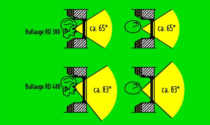
We always recommend installing two bulls eyes. The illumination is provided by the smaller bulls eye. The second bulls eye allows a glare-free view of the illuminated interior. The RD 400 with the large viewing angle is particularly suitable for large containers with a variable filling level. Several agitators can be monitored with one panorama unit. Bulls eye RD 300 / RD 400

Bulls eye RD 300
- Parts of the RD 300 bulls eye
1. Integrated ring seal of rubber and stainless steel 316 for direct, pressure
resistant installation in core hole or spacing tube of 300 mm Ø
2. Special glass 250 mm Ø, 15 mm
3. Wiper, wiper scope 230 mm Ø
4. Spray nozzle made of stainless steel 316
5. 3 stainless steel mounting brackets

Bulls eye RD 400
- 1. Integrated ring seal of rubber and stainless
steel 316 for direct, pressure
resistant installation in core hole or spacing tube of 400 mm Ø
2. Special glass 350 mm Ø, 15 mm
3. Wiper, wiper scope 330 mm Ø
4. Spray nozzle made of stainless steel 316
5. 4 stainless steel mounting brackets

Special designs: Bulls eye in immersion pipe
-
Bulls eye on stainless steel plate
Plate can be manufactured in many sizes with fixing holes to customer specification.
Bulls eye for existing on-site plateRD 300 and RD 400 available as a kit with CAD data for cutting the on-site plate.
Bulls eye for membrane materialsRD 300 and RD 400 available as a kit for installation into a membrane roof.
Accessories

Inspection lamp
- ATEX II 2 GEx (zone 1+2)
230 Volt, 50 W, aluminium casing with push button and timer.
Type: LUMI USL07 - EX, bulb halogen 12 V, including parts for fixed mounting at the bull's eye

Gimbal lamp holder
- Gimbal lamp holder for 2-axis movement, bolted directly to the bulls eye, for optimum handling of the EX-light for RD 300 / RD 400 bulls eyes

Rosette
- Stainless steel 304 rosette for a clean finish to the tank cladding. Length 20 cm, collar 5 cm . Attachment and eventual shortening on site.

Sun protection cover
- Sun protective cover on the tank wall as a darkroom for better viewing through the bulls eye, 58 x 58 x 114 cm, 2 mm aluminium sheet, including fixing gutter attachment on site.
Over-/ under-pressure valve ÜU TT
Over-/ under-pressure valve ÜU TT
- The valve features an immersion cups and two sealing
fluid chambers, one for over pressure and one for under pressure. The
response pressures for over-pressure and under-pressure can be set
independently of each other. The response pressures are determined via the
weight of the respective immersion cup.
The maximum filling level of the sealing fluid is determined by the height of the internal chamber standpipe. Additional water which has accumulated from condensation or rainwater runs off outside automatically.
For the gas, escaping at over pressure a flange is provided, to which a discharge pipe (optional) is connected.
Upon actuation of the underpressure valve, external air flows through air intake opening into the gas line.
The filling level of the overpressure cup (above) can be controlled via an immersion pipe. Filling level of the underpressure cup (below) can be controlled at the inspection glass.
At the upper gas inlet, a ½ "connection is to be found e.g. for cleaning (rinsing), topping up, for sampling or to connect a pressure gauge.
Response to over-pressure
With increasing pressure on the gas side, the pressure cup is raised (above) and after emersion from the sealing liquid, the gas can flow through and escape through the blow-off pipe. The vacuum cup remains closed.
Response to under-pressure
Conversely at under-pressure, the vacuum cup is raised (below) and after emersion from the barrier fluid, air can flow into the control valve and into the gas line. The pressure cup remains closed.
Heat insulation
The over-,under-pressure valve is thermally insulated with a rubber flex insulation. The insulation is resistant to moisture, closed and flame retardant. The thermal insulation is covered with a protective cover made of stainless steel sheet.
Dimensions
We offer three different sizes for the over-, under-pressure OP TT. These depend on the respective flow amounts:- ÜU TT 150 for gas amounts up to 150 m3/h at 3 mbar pressure response
- ÜU TT 200 for gas amounts up to 220 m3/h at 3 mbar pressure response
- ÜU TT 273 and OP TT 300 for gas amounts up to 600 m3/h at 3 mbar pressure response
Accessories
Over-pressure outflow pipe with flange
- V2A DN 150 / DN 200 / DN 250 / DN 300, 2 m long. If required other lengths can be supplied.
Warning signs Ex INTERNATIONAL on 304-plates
- Complete with clamp pipes DN 150 / DN 200 / DN 250 / DN 300
Connection Tee for over-pressure and under-pressure ÜU TT in PE-HD
- Polyethylen piping complete with 316 steel blind disc, gasket and screws. DIN flange PN10
Connection Tee for over-, under-pressure valve ÜU TT 150 and 200 in stainless steel 316,
- Tee connection for over-, under-pressure ÜU TT 150 / 200 in V4A, complete with V4A dummy wafer, VA gasket and screws. V4A DIN flange DN 150 / DN 200 for direct connection of the valve, produced totally in VA.
Gas valve, butterfly
- EBRO stainless steel / NBR sealing rubber for gas.
Gooseneck
- for over-pressure and under-pressure ÜU TT 150/TT 200/TT 273, consisting of KG 2000-fit socket fittings to plug onto the connection tee inside the tank to prevent entry of substrate . Complete with stainless steel clamp and stainless steel V4A profile including fasteners.
Over-pressure sensor for ÜU TT150/200/273/300
- Sensor for trigging a signal at over pressure opening, consisting of stainless steel adapter DN 150/DN 200/DN 250/DN 300, mounting bracket and ATEX-proximity sensor with 2 m cable and seperate amplifier box gasket and screws.
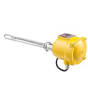
Heater for ÜU TT
- electric immersion heater TPAE, 200 W 220V 1Ph, Ex d II C T1 Ex II 2 GD, with BROAE 87 connection box Ex d II C IP67
Warnschilder ExZone 1+2 auf V2A-Trägerplatten
- Komplett mit Rohrschellen DN 150 / DN 200 / DN 250 / DN 300.
Underpressure sensor for ÜU TT 150/200/273/300
- Sensor for trigging a signal at underpressure opening, consisting of stainless mounting bracket and ATEX-proximity sensor with 2 m cable and seperate amplifier box gasket and screws.
Over-/ under-pressure ÜU GD
- The over-/ under-pressure valve ÜU GD serves to
regulate the over-/ under-pressure in the fermenter of a biogas plant. The
high and low pressure protection ÜU GD 150/200 has a stainless steel
container with a barrier liquid and partition plate between the gas space
and airspace.
In the inspection glass the operator can see at a glance- If the barrier fluid is contaminated
- The current gas pressure
- The current valve setting for maximum pressure
- If gas is being expelled
Operating principle:
In the case of increasing pressure on the gas side of the fermenter, the liquid level in the gas space of the over-, under-pressure valve is pressed down until the biogas can pass under the partition plate, and escapes to the air space through and the blow off pipe. Conversely in the case of under-pressure the liquid level on the air side can be pressed down to let air pass to the gas side of the fermenter. Thus, a possible unapproved under-pressure is reduced in the fermenter. The chamber parameters are designed so that at a chosen adjustment of the set pressure for the response pressure is always twice as large. The maximum level of the sealing liquid is set by an overflow pipe. Condensation or rain water entering can run off through the overflow pipe automatically. The height of the liquid level determines the set pressure at which the gas (over-pressure) or air is allowed to pass (in the case of under-pressure. In the case of increasing pressure through accummulated condensation or rain water excess sealing liquid is first pushed out through the overflow pipe.
Important note:
The outlet pipe must always remain open to allow excess condensate to be able to drain away. Because of the risk of freezing and empty sucking by the siphon, only an open channel and not a tube should be used for removal of the condensate!
Dimensions
We offer two different sizes for the over and-under pressure seals:- ÜU seal 150 for amounts of gas up to 125 m3/h
- ÜU seal 200 for amounts of gas up to 200 m3/h
Accessories
ÜU GD 150 / ÜU GD 200
- Over- / under pressure valves made from stainless steel with cover 83 x 125 cm for gas dome and gas amounts up to 125 m³/h /200 m³ /h, 4 mm thick, 1 opening for over-pressure washer 40 x 40 cm with gasket, nuts and washers for blow-off including instruction manual.
Blow off pipe with flange
- Stainless steel 304 DN 150 / DN 200 , 3 m long. Other lengths available if required.
Warning signs "Ex zone 1+2 double on V2A plates"
- DN 150 / DN 200 complete.
Warning signs "Ex international double on 304 plates with pipe clamps"
- DN 150 / DN 200 complete.
Level sensor E+H Liquipoint T FTW31
- ATEX, WHG-certificat, with relay-switch FTW325 and 6/4" coupling i-a, conic seal, stainless 316
Frame case gas dome
- Cover dimensions 83 x 125 7height 65 mm, 75 x 115 cm clear opening,stainless steel 316, 3 mm thickness, U-shaped profile with a double rib.
Additional price for flange connection on the side of the gas dome
- DN 150-DIN / DN 200-PN10-DIN flange, stainless steel 316.
Gas valve, butterfly
- DN 150 / DN 200 EBRO cast iron / stainless steel / NBR for gas.
C clamps
- Complete stainless steel 304 threaded hole M8, 20 mm wide, 28 mm grip range bent.
Foam rubber gasket
- 35 x 4 mm, Tapetec (1 roll = 10 m, Sahlberg).
Over-pressure plate
- 48 x 48 cm stainless steel incl. press on frame, side seal groove and travel stop.
Over-pressure plate with sight glass
- Stainless steel sheet 48 x 48 cm with integrated sight glass with wiper including press on frame, side seal and travel stop.
Ballast weight for over-pressure plate
- Consisting of rubber washer package Ø 24 cm, pieces of 2 cm hole with tape for fastening.
Air dosing unit
Standard equipment
- Sulphur in biogas causes problems during combustion in the CHP.
Desulphurization is useful. Using an air dosing unit it is possible to feed
small amounts of oxygen into the digester tank.
Desulphurization of biogas takes place within the digester through the activity of naturally occurring bacteria that use the hydrogen sulphide in their metabolism and deposit elemental sulphur. They need a small amount of oxygen. To this end an air pump blows a small amount of air into the gas space in the digester. The amount of air should be about 4-6% of the amount of gas produced.
The full effect of desulphurization is attained after several weeks, when a gas biofilm of hydrogen sulfide consuming bacteria is formed on the surfaces. This is facilitated by higher temperatures, wetting the surfaces with slurry/substrate by rough surfaces.
Part of the air dosing unit
1.Air pump for continuous operation
2.Air flowmeter device
3.Throttling valve to regulate the volume
4.Connection with ball valve for condensate drainage and pipe rinsing
5.Air nozzle with non-return valve
Dimensions- Type 20 for amounts of air up to 20 l/min
- Type 40 for air amounts up to 40 l/min
- Type 120 for air amounts up to 120 l/min
Accessories

Air nozzle for desulphurization
- Consisting of stainless steel tube 12 x 1 mm, 0.5 m, VA elbow for 20 mm PE-HD tube, with stainless steel non-return valve, with flange for sealing.

Sealing glue cartridge
- 310 ml / Sabesto.

Sikaflex TS Plus
- Sealing compound 600 ml bag for sealing.

Air dosing unit for biogas desulphurization size 40
- up to about 1100 cubic meters of biogas per day, consisting of variable-flow display of up to 40 liters/min, linear air pump LA-45B, throttle valve, 2 ball valves with connection coupling for 20 mm PE high pressure air hose, 1 connection for condensate drain and for pipe rinsing. Incl. operating instructions in German. The vents must be equipped with a non-return valve!

Air dosing unit for biogas desulphurization size 120
- up to 3000 cubic meters of biogas per day, consisting of: 3 variable flow displays up to 120 liters/min, linear air pump LA-120B, 130W, throttle valve, 3 ball valves with connector for 20 mm PE-HD air hose, 3 connectors for condensate drain and pipe flushing. Incl. Operating instructions in German. The vents must be equipped with a non-return valve!
Unit for measuring

Measuring unit
-
Each digester should be equipped with a possibility for removal of substrate samples. The BIOGASKONTOR measuring unit provides safe discharge samples with double ball valves made of stainless steel. A measurement point for the temperature and the pressure or the fill level in the vessel is available.
Variations: DN 150 with flanged pipe connections for building-shaft lining or stainless steel plate for direct screw to wall.

Measuring unit fitting set with ball-valves
- Consisting of fittings for sample outlet and pressure measurement. Complete of stainless steel 316

Measuring unit
- Comprising DN 150. flange bearing with stainless steel lid including probe conduit for temperature sensor and 2" pipe without anchor bolt for fixing without temperature and pressure can.

Spacing bush
- DN 150 for 160 mm conical pipe rubber seal length 240 mm.

Steel plate unit 3mm
- 35 x 35 cm with hole circle for dowelling to tank wall, stainless steel 304, including sensor conduit for temperature sensor, 2 "socket without sealing and fastening material.

Pressure sensor for level measurement
- Pressure transmitter DMU 03 VM, without display, piezo-resistive stainless steel sensor, accuracy: 0.25% FSO. Stainless steel 316, 1.4571 / 1.4435, Process connection: 1/2 ", power supply: 12-36 V DC, output 4 - 20 mA, system: 2-wire, electrical connection: Plug DIN 43650-A, Measurement range: 0-1 bar (used for measurement unit).

Temperature sensor PT 100
- GTF200 4 lead sensor, 4m cable, for GREISINGER GIR 2002 and GIA 2000.

Temperature controller including temperature display
- GREISINGER GIR 2002 without 4-lead sensor PT 100, 230 V power supply, 2 relay outputs, serial interface bus operating mode..

Thermometer GREISINGER GIA 2000
- With 4 lead sensor PT 100, extendable to 100 m, min / max-storage, 240 V, precision 0,1 °C.
Warning signs

Warning sign "explosive atmosphere" D-W021
- Triangle with EX label, aluminium type, 165 mm x 190 mm

Warning sign "Observe noise protection"
- ISO7010-M003Plastic sign, Ø 200 mm

Warning sign "Access prohibited" D-P006
- Aluminium type, Ø 200 mm

Warning sign "No open flames" D-P002
- Aluminium type, Ø 200 mm

Warning sign "Fire extinguisher"
- PVC 200 mm x 200 mm

Warning sign "Biogas international, incl. 2 symbols D-W021 + D-P002"
- Aluminium type, Ø 300 mm x 400 mm

Warning signs "Ex international double on V2A plates with pipe clamps"
- DN 150 / DN 200 complete

Warning signs Ex INTERNATIONAL single on V2A-plates
- Complete with clamp pipes DN 150 / DN 200 / DN 250 / DN 300.

Warning sign duct label "Biogas sticker"
- 25 mm x 155 mm

Warning sign duct label "Substrate sticker"
- 25 mm x 155 mm


